I want to know if it’s possible to control a brushless motor (for RC projects) using the Cyberbricks system.
I believe it’s theoretically possible because if the Cyberbrick can control servo motors, then it should be able to control a brushless motor because it’s code is similar to servos(in the Arduino IDE perspective).
I just wanna know if anyone has actually tried it out since I haven’t seen any documentation or videos of someone making a RC vehicle using a brushless motor. If anyone has any advice for actually attempting it, let me know!
You can use arbitrary PWM input signal capable brushless ESC with CyberBrick. CyberBrick can output (with std. official MicroPython code) from 0.5ms to 2.5ms pulse length width servo signal.
Exactly. The servo outputs of CyberBrick are nothing more than extended servo range PWM outputs, as available on any arbitrary R/C model receiver intended for controlling servos and other accessories via 3-pin “servo” connector.
Unfortunately, its not as straight-forward as it looks…
After plugging the esc in one of servo ports and setting up a simple configuration, the esc, instead of spinning the motor, would instead play random musical beats (maybe to indicate failure) instead. I think the problem here is that I don’t know how my esc actually works (I am quite the amateur ) but I can’t find any relevant documentation that I can use as an answer.
RC ESCs often require an arming sequence before they start spinning. Typically hold at full throttle for a moment then hold at zero throttle for a moment. This is to prevent accidentally chopping fingers off with a prop.
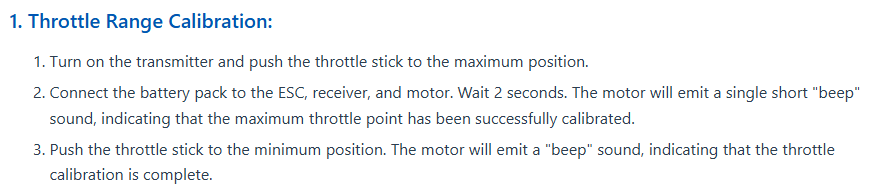
Honestly yeah, I think that’s where my problem is. For now I am looking for documentation on how to start an arming sequence on my ESC specifically. For now I found this part of a documentation:
The other problem I have is that right now I have to use two batteries to power up the ESC and the CyberBrick core (with the receiver shield). Because the ESC has BEC I would assume it would power up the core just fine but I still need a second battery to power it…
Maybe its how I have to turn on the core first and then plug the battery to the ESC that keeps causing the arming issue.
You can pull out the red/middle pin on the 3-pin servo connector to not power the CyberBrick via ESC BEC. Be sure to isolate it nicely, e.g. with some heat-shrink tubing for it to not touch anything, as ESC will try to supply 5V over it.
If you are using a 2-cell LiPo battery for your ESC, then just wire the X11 receiver shield battery pins parallel to it from your ESC. If you use more cells than 2, then keep in mind that the X11 is rated at max. 12.6V, so be sure NOT to exceed this, otherwise the blue magic smoke will come out of it and then the genie is off the bottle and your device not working anymore.
Yes, your battery is fine. Just make an appropriate Y-shaped wire harness with one fork having 2 pin JST XH2.54 connector (100mm Wire with 2Pin XH2.54 Connectors (2PCS) | Bambu Lab US Store), like the original BambuLab/CyberBrick battery has and power this way your CyberBrick X11/A11 Combo, while disconnecting the middle/red servo pin wire on the ESC connection to X11.
Also keep in mind that the output range of CyberBrick servo pins is 0.5ms to 2.5ms (Where is documentation on building applications for Cyberbrick? - #23 by xrk), which is higher than “normal” R/C models, which typically use 1.0 to 2.0 millisecond long pulse to control a channel. Thus if you are driving over the 1.0 and 2.0 ranges, some ESCs might not correctly initialize.
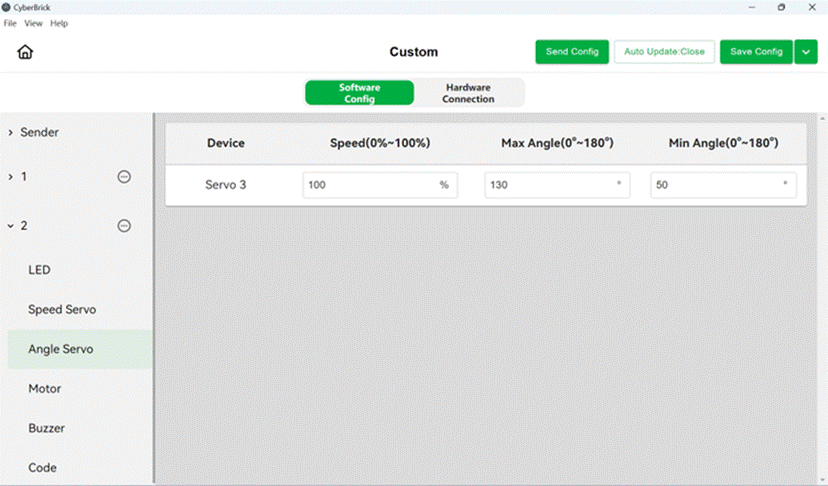
One option would be to modify the MicroPython code, that runs on CyberBrick Code. By default the set_angle() code is:
The values above result the duty being driven from 25 to 127 in full 1024 step range for the full 20ms PWM period, resulting in 25/1024 * 20=0.49ms to 127/1024 * 20=2.48ms servo pulse range for 0 to 180 degree input (variable angle) value.
If you want to limit your CyberBrick to output only 1.0 to 2.0 ms “standard” R/C range, modify the codeline to use: duty = (int)(angle*51/180 + 51)
instead, which results to 51/1024 * 20 = 1.0ms to 102/1024 * 20=2.0ms range.
@xrk I have installed Arduino Lab for MicroPython but I still don’t know how to access the internal file system of my CyberBrick core (I am very new to this)
After installing the Arduino Lab for MicroPython, attach via USB-C cable your CyberBrick Core to your computer, start Arduino Lab for MicroPython, give some writable folder, when asked. In the IDE hit connect and then navigate to Files (Files folder button in the upper right). You should see subfolder bbl, double click to enter it. There you should see servos.py MicroPython file, select it and now click “Edit” in the middle of the two panes (uppermost icon with a pen and notebook). Do your duty variable calculation edit (at line 71 in the version that is factory saved on the CyberBrick Core) and hit Save.
So I FINALLY figured out how to get my ESC to configure with my CyberBrick. I decided to follow @xrk advice of attaching my ESC without the power pin (in order to stop it from getting powered by the CyberBrick core) which let me start the ESC properly.
In order to configure it, I had to move the joystick DOWNWARDS instead of upwards (I thought I had to set it upwards to configure the maximum range); This is probably only specific to my ESC only so this solution may not work for everyone.
I’ll still try out xrk’s 1.0-2.0ms range hack and also create the Y-shaped wire harness for my battery
Makes sense that you had to keep your throttle stick down, as the default CyberBrick official remote has the joysticks ordered this way, that the longest pulse width is output, when the sticks (left or right, does not matter) are down. For more, see: Where is documentation on building applications for Cyberbrick? - #31 by xrk where I did some measurements of the outputs.
This is in a way in reverse to “normal” R/C systems.
That the system in numerous ways does not behave like one is used to with R/C models, gave me reason to develop something way better: Controlling CyberBrick models from EdgeTX radio
RC ESCs all require “minimum throttle” in order to arm. On a model plane, you’d have to hold the throttle stick closed/down after powering up to get the ESC to arm. It’ll play tunes when it’s connected, it should beep to tell you how many battery cells it thinks you’re using (assuming 3.7V/cell, it does the math). But after the initialization beeps it’ll wait to see that low throttle input before it will arm to allow the motor to spin. On an airplane, this keeps the prop from chopping your arm off if you mistakenly connect the battery with the throttle at a non-zero position.
If you limit the angles from min 45° to max 135° (middle 90° position plus/minus 45°), you should also get 1.0 to 2.0 ms pulse output, as usually expected from R/C model ESCs.
And you should also be able to reverse the function, to have a short pulse (1.0 ms), as typically expected for ESC idle input-command, at stick down position and high pulse (2.0 ms for full throttle) at stick up position, by negating the direction: