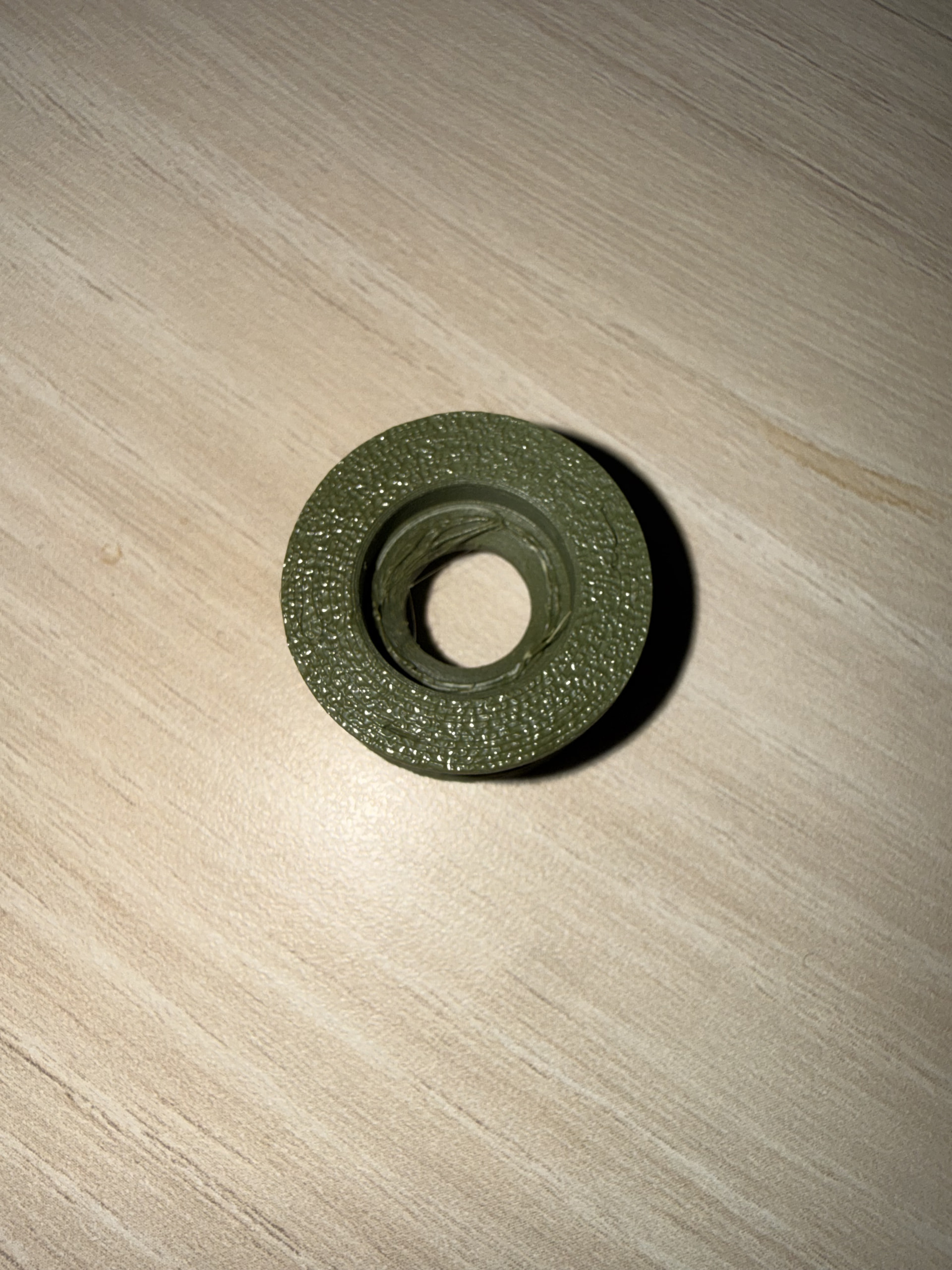
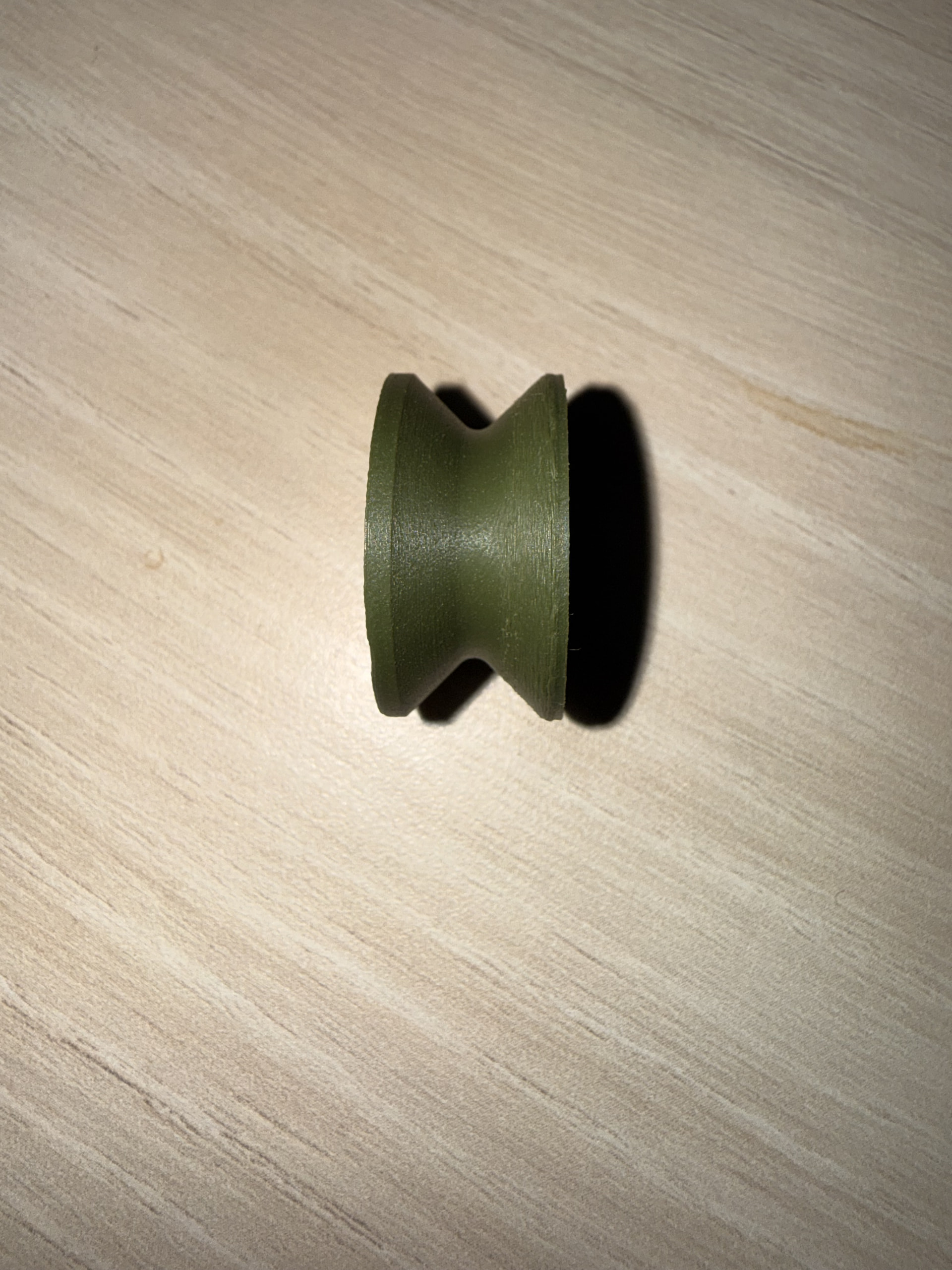
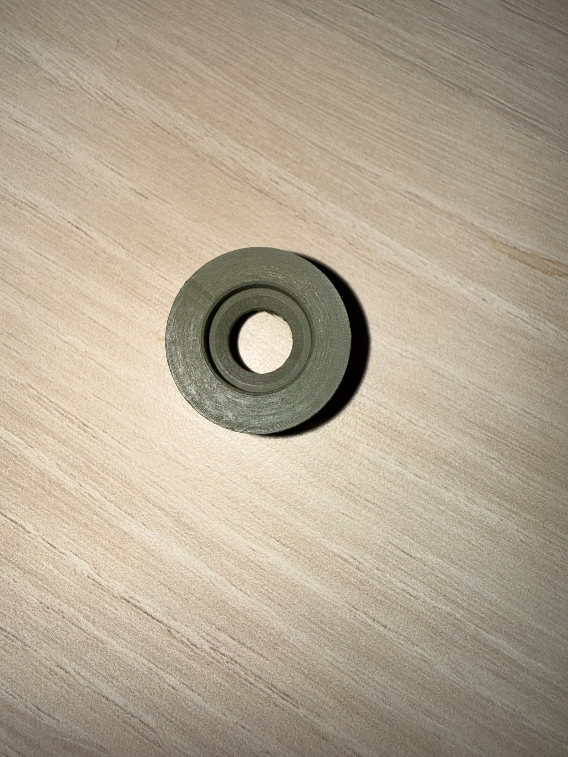
I’m printing a small rope pulley and the upper side of the groove never comes out as clean as the lower side. I’d like your advice on preset settings or design changes that fix this.
Part:
24 mm diameter, 12 mm wide, 2.5 mm rope
Symmetric V-groove, about 4 mm deep, with a rounded bottom (R ≈ 1.3 mm) and 45° flanks on both sides
Two MR148 bearings (8×14×4), press-fit from both faces
Printed flat (axis vertical), single piece, no supports
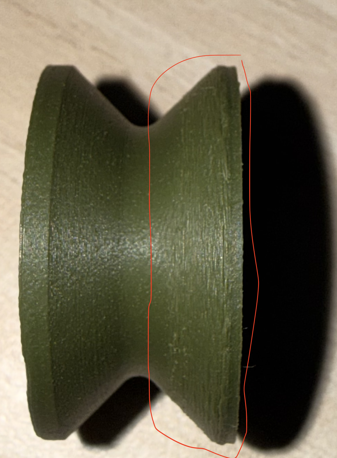
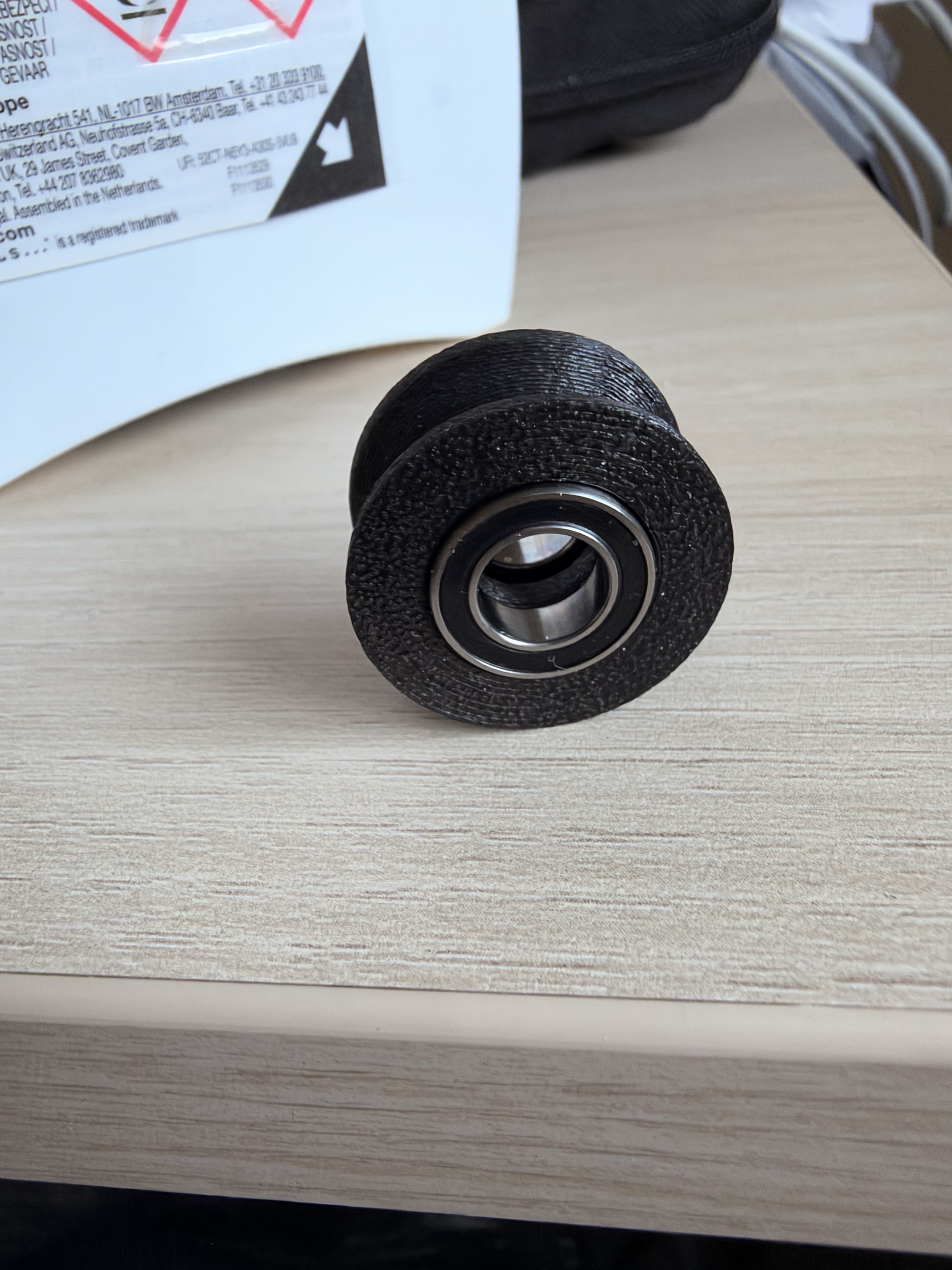
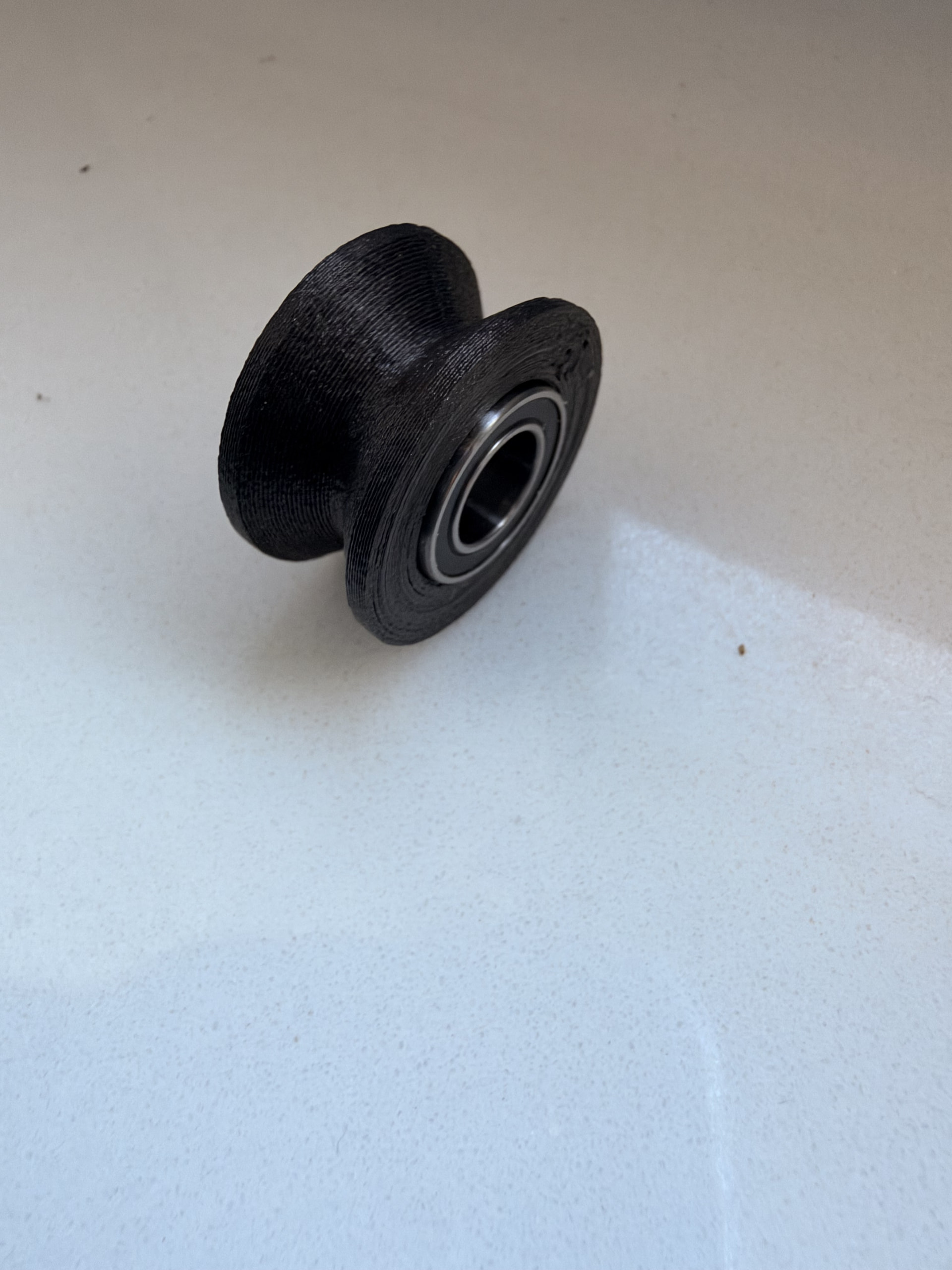
The problem: the lower flank of the groove faces up and prints smooth. The upper flank is a 45° overhang, and it comes out rough and slightly droopy, especially the thin edge of the upper flange at the rim. On an earlier version with about 26° flanks, the upper side sagged badly. Moving to 45° improved it, but it’s still not perfect.
Preset: Which overhang settings make the biggest difference for a 45° circular overhang on the X1C? For example overhang speeds per angle range, overhang threshold, cooling, outer wall line width or flow.
Variable layer height: Has anyone used thinner layers (0.08–0.12 mm) only in the groove area? Was the improvement worth it?
Wall order: Does inner/outer vs outer/inner wall order matter for overhang quality here?
Design: Would you change the geometry instead? For example a teardrop-shaped groove, a small chamfer on the flange rim, a thicker flange edge, or a steeper angle (50–55°) at the cost of groove depth?
Alternatives: Has anyone printed the pulley as two halves (outer faces on the bed, glued together) or used a PLA/PETG support interface in the groove? How did it compare?
I’ve attached photos of the upper and lower sides of the groove and a cross-section of the model. Happy to share the .scad file.
This question could have been asked in a single sentence “how can I improve the surface the bearing sits against?”, add the pictures, done.
It’s a sad state of affairs when people’s only goal is to write a lot, rather than writing well.
Anyhow…calming breath…
Your bearing lip only needs to be wide enough to catch the outer bearing race. You’re going through a lot of unnecessary consternation improving a surface that mostly doesn’t need to be there.
Yes, you could use an interface material. Just make sure your purge quantity is enough to make sure there’s no trace of the release material left to contaminate the remaining print.
You can also print as two halves, assuming there’s a bolt running through it - if it’s putting enough preload on the two halves you won’t need to glue, even.
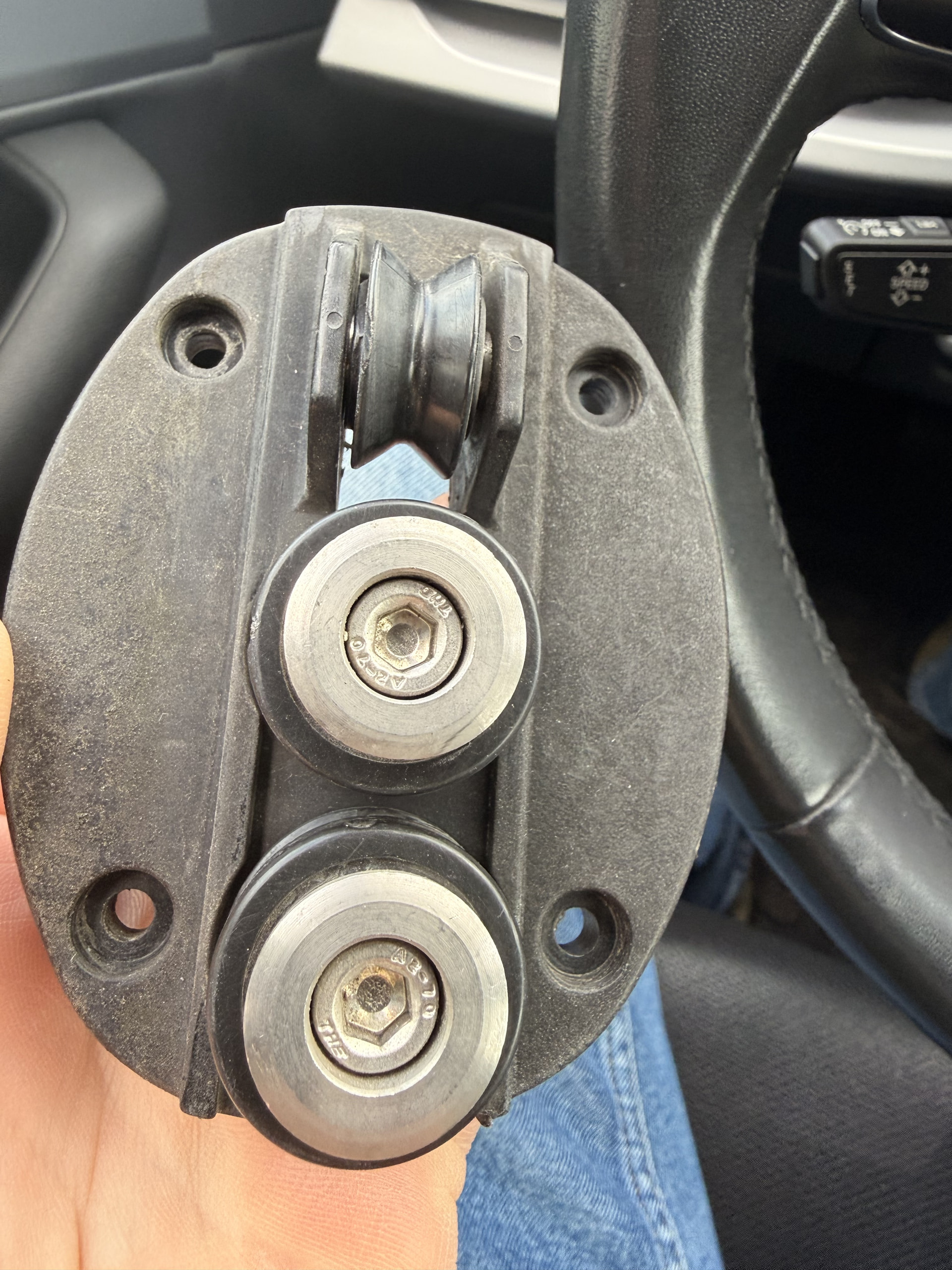
I don’t think it’s a good idea to glue this together because I’ll eventually be printing with PA6-CF, and this spool needs to withstand a really heavy load. Actually, the top part of this spool is a problem for me—I’ve already tried many different settings. I always print flat, but as you can see, there isn’t enough support.
If this is a safety or mission critical item, it probably shouldn’t be printed at all. Sheaves are commodity items, cheap and readily available from the usual suspects.
Also - the analysis needs to account for more than just the sheave itself, it needs to consider the frame, bearings, and the shaft as well. I’d argue the a proper frame/shaft/bearing design could be printed in two pieces and wouldn’t need glue at all.
…and for the record, the right adhesive is going to be stronger than the interlayer adhesion for the material itself.
Intent aside, IMHO it looks pretty good already. There’s always sanding, for a finer surface. Shorter layers will give a smoother finish on any sloped or domed surface (I’ve gone to 0.4mm height on my H2C with success). Slow it (esp. walls) down even more.
However IMHO if you’re going to use CF nylon for the final piece, the time testing this with other materials (completely dissimilar) is at least partly wasted. Overhang performance is going to vary significantly with material. So is the surface finish. And probably tolerances. (And do you really want CF/GF for a rope race? Very abrasive.)
Cheers,
-Max
PS. Check if you really want “precise Z height” enabled. It only adjusts the final few layers to achieve the final original model height, making them variable and less predictable. For precision, ideally the model is already sized for a particular layer height, or a multiple (eg. .10, .4, etc).
I think this is the most durable material (and it will work well here); this is what the component looks like, and as this roller carries heavy loads, bearings are used instead of just a plain sleeve.
Made me think of this stuff that I recently ran into, supposedly the CF fibers are confined to the core of the material somehow and don’t surface. They have an ABS like that also, for ~ half the price. (Not an endorsement, and have not tried either material.)
I’d be worried about load failure if you cut/glue it, but idk how much weight this pulley sees.
I’d also be mildly worried about using a CF/GF filament due to abrasion but its probably also the cheat code that’ll get you the cleaner overhang, so yknow.
If able to, you can probably reduce that angle’s severity by about 5 degrees and itll fix itself, it’s very close to the critical angle
Alternative strategies would be to assign line width == nozzle diameter, and layer height == very small, which sometimes gets better results due to each layers’ lip not protruding very far
PPA-CF is usually very brittle, and will have a hard time getting through the bends in the tubes without breaking. All the tubes, not just the AMS.
You referenced X1c, You will likely also have to add a top riser to the machine to give it a more gentle final bend down into the extruder, and unhook the PTFE tube from the chain snake.
This wiki is phrased with H2 in mind but conceptually all the same