Hello,
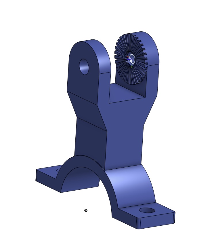
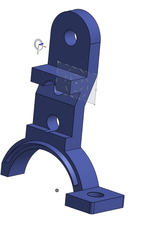
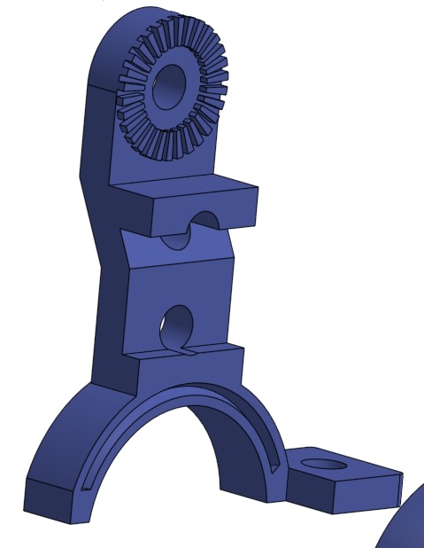
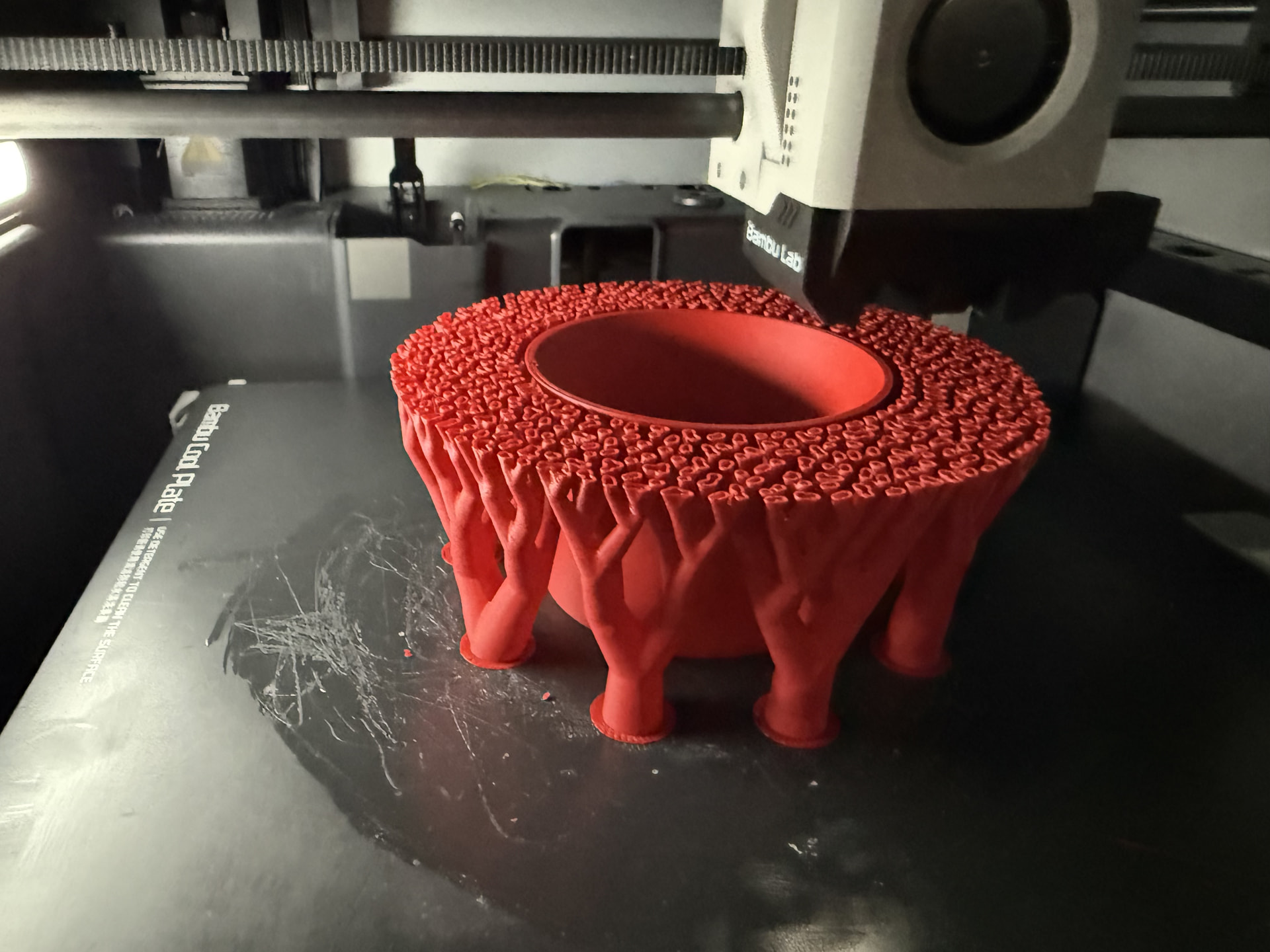
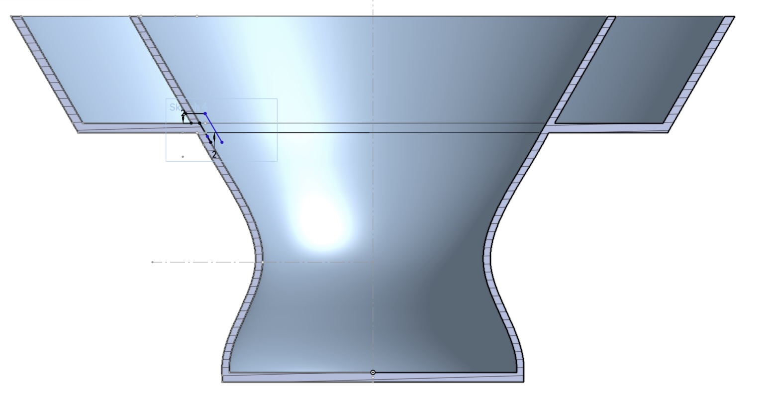
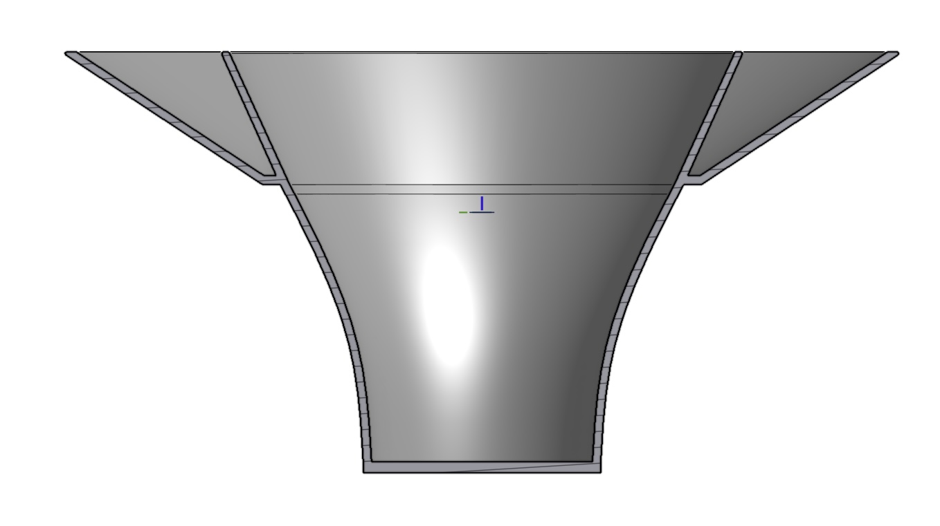
How can I print this adapter so that the ribbed surface is printed cleanly and isn’t blocked by support material?
Kind regards
ProApe
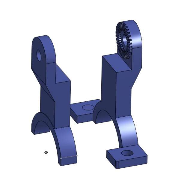
I would cut it into two halfs in the middle ending over the half tube on the bottom, so the screwholes are not cutted.
print the halfs seperately and glue or screw them together.
How I would print this depends on 1) the actual size of the part and 2) the loading and use scenarios for the part. To a lesser extent, those drive the material I would use, and that impacts how I would print it as well.
That said, this design isn’t great for FDM 3D printing. I suspect the toothed section is supposed to allow another part to be positioned at various angles there; if that’s the case it won’t work. Teeth are too deep, and the yoke wont be able to allow a part to be inserted or rotated without just shearing the teeth - unless you’re using some kind of spring design with a lot of movement, but even still, these teeth aren’t great for printing. I’d use fewer teeth, and a profile that doesn’t use overhangs at all.
If I absolutely had to print this as-is, I’d orient it exactly like that, and use support interface material to make removal easy. Possibly tip it to 45 degrees to the plate to improve layer strength.
Hello,
It’s not very big: it’s 61 mm high, and the teeth are 1 mm wide on the broad side and 0.6 mm on the narrow side. I’ve made sure not to go below the nozzle’s 0.4 mm.
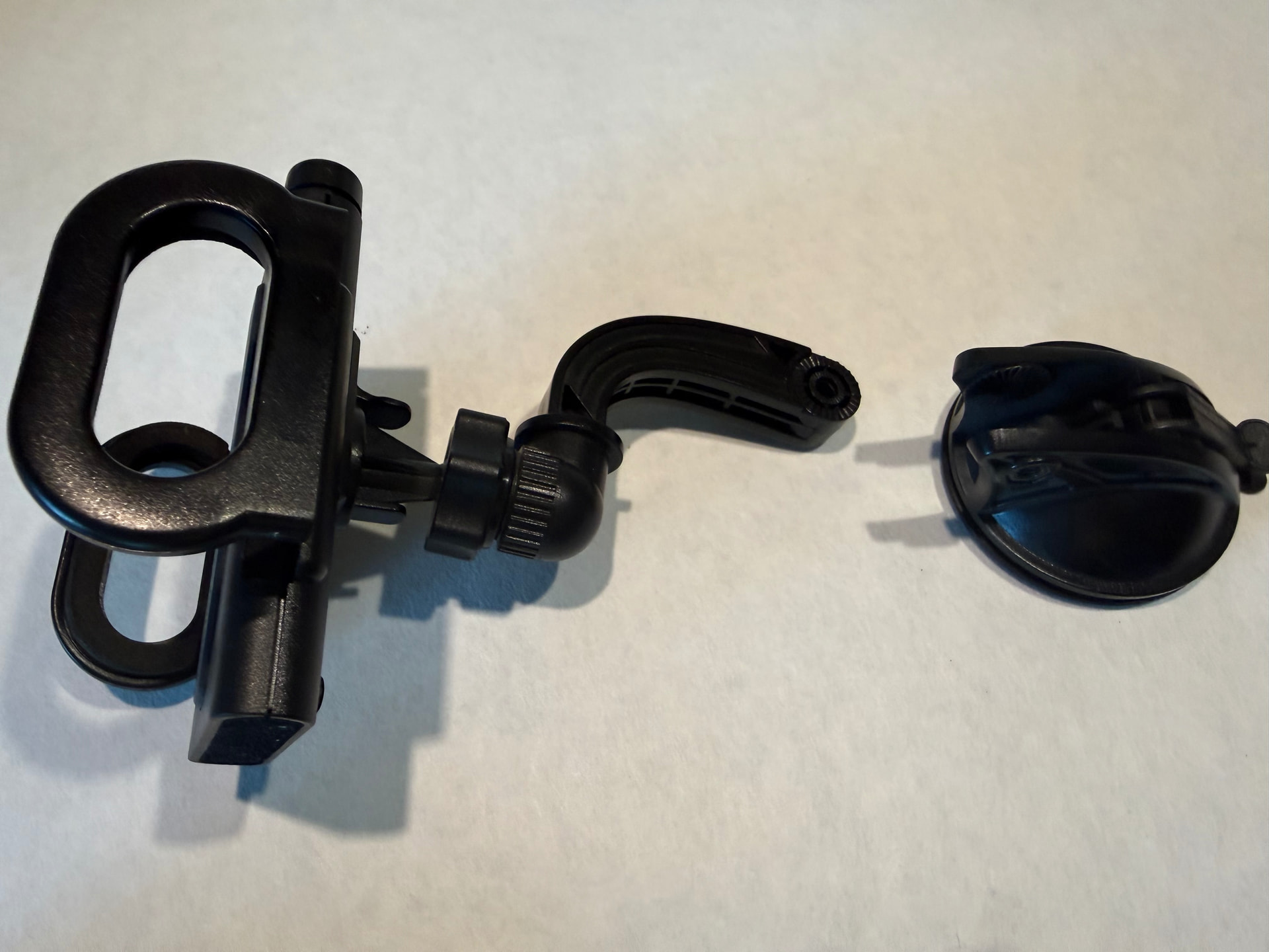
I have a mount for attaching the mobile phone to the windscreen using a vacuum. It consists of two parts: the windscreen attachment and the part for the mobile phone.
The windscreen attachment is to be replaced by this adapter for a bicycle’s handlebar.
You’re right!
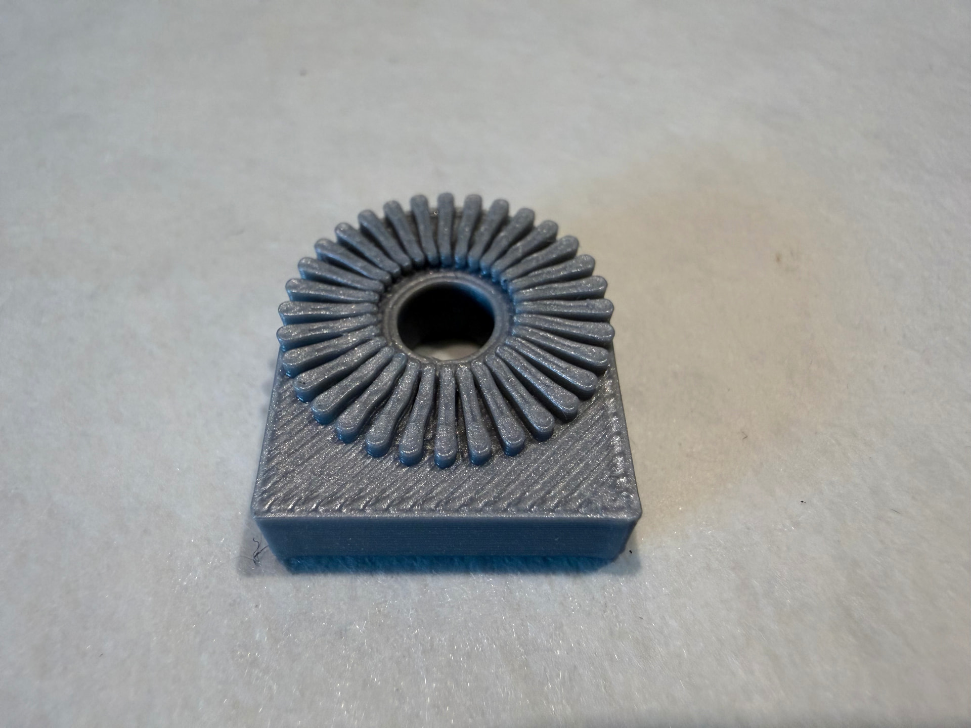
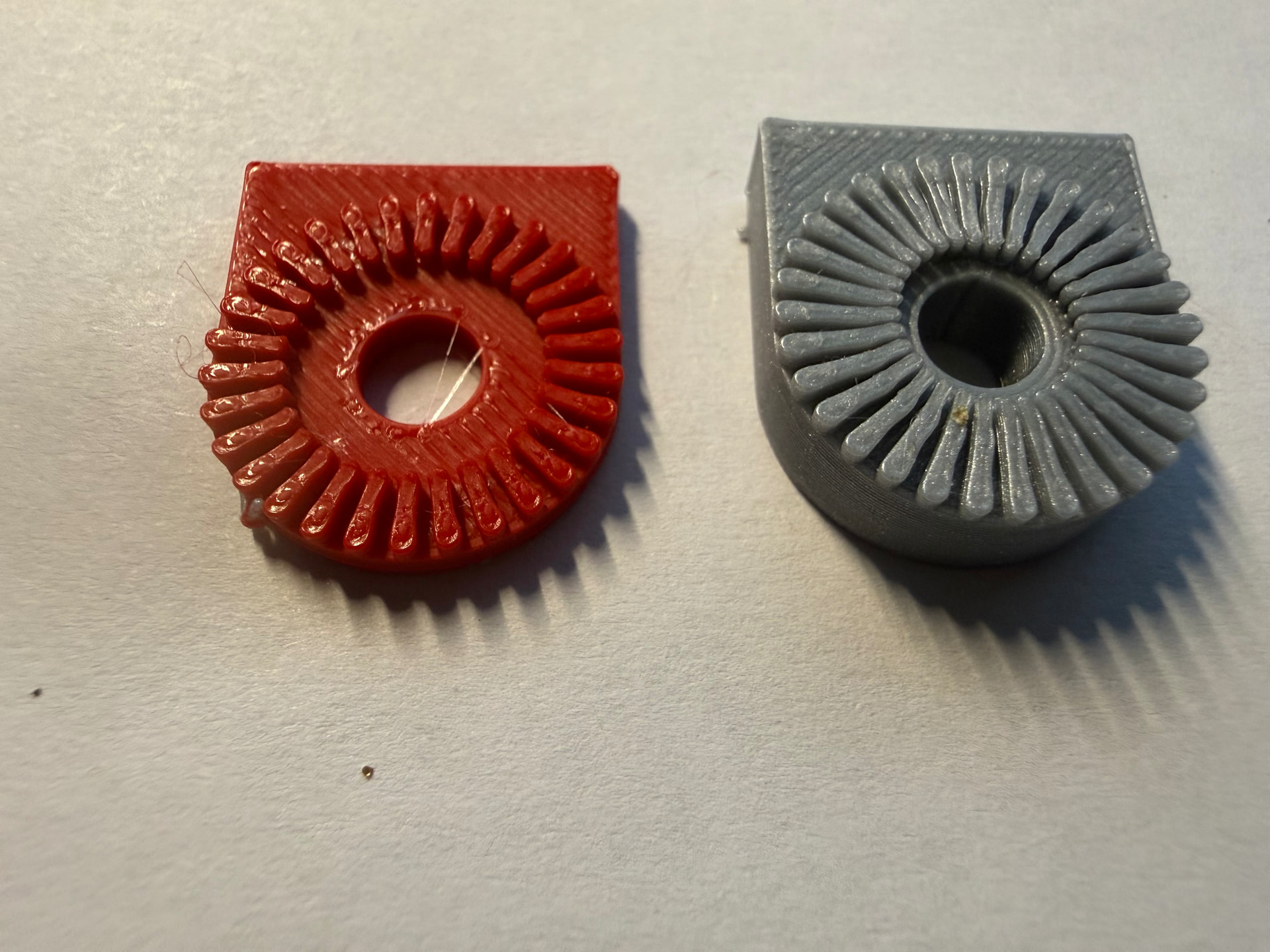
I’ve printed a small part with the teeth; it’s not perfect, but it’s better than a smooth surface.
However, I’d like to improve it if possible, although I’m limited by the 0.4 mm diameter of the nozzle. I surely should use a finer one for that.
But my main problem is: how to print it?
______________
I’ve just realised, by counting them on the enlarged photo, that the number of ribs isn’t 32: there are only 30; I’ll correct that and that should improve things a bit.
Kind regards
Obviously I don’t know exactly what this part is for or what those ribs mate with, but I would suggest considering making them triangular instead of squared off ribs. If there are any imperfections (and there will be) the squared off ribs might prevent it mating properly, but if they were triangular ribs that come to a point then whatever it mates with will self align and fit in as well as it can instead of just not fitting at all.
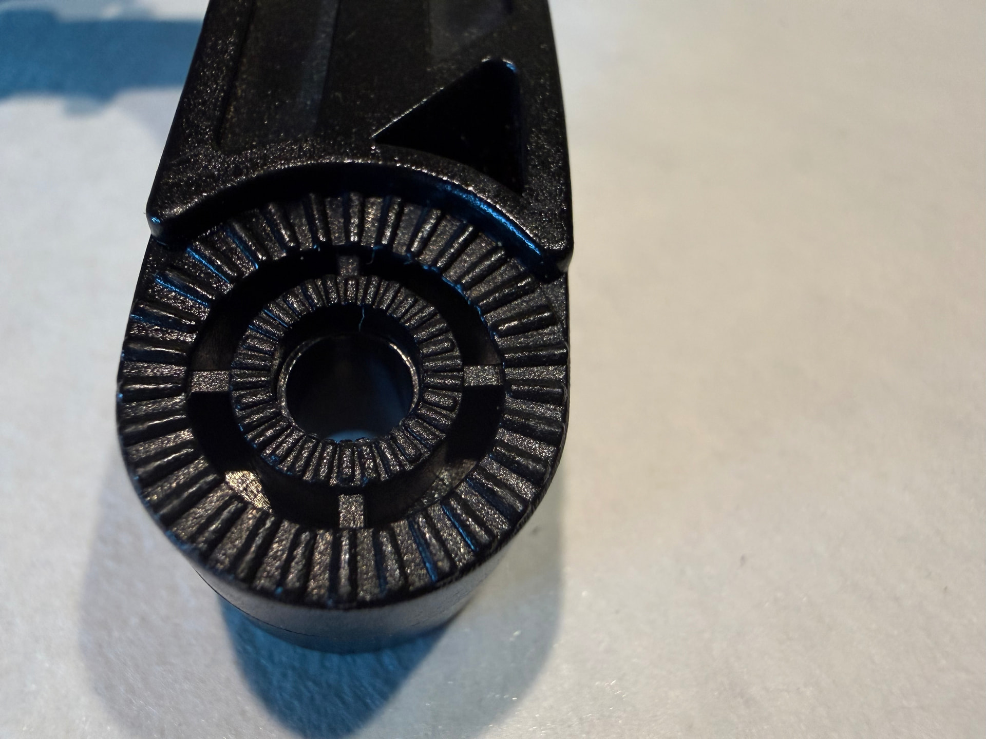
I’ve tried to replicate the original ribs. They rub against the ribs on the windscreen component (see IMG_5632), making it easier to maintain the set position than if two smooth, flat surfaces were rubbing against each other.
However, this is a common method for this situation.
And do you think triangles would create more friction on these ribs?
I think the triangles might increase the chances of the parts meshing and locking together instead of ending up floating on the top surfaces which would mean less hold. But that’s the point of owning a 3D printer - you can try both and see which works better in reality.
Well, at these dimensions, I’m limited to a minimum of 0.4 mm.
If not ribs, why not a number of spikes? They should provide even better grip.
I’m getting used to the idea of splitting the finished piece into two parts and have started working on high-relief and bas-relief joints to make the parts easier to assemble – although that probably wouldn’t be necessary as there are screws, but it’s a challenge in Onshape.
Which printer are you using?
My printer is the X1 Carbon with AMS
If you make the back of this part flat. In other words, make the base just as wide as the top, you can lay it flat on the bed.
OK, I had that idea afterwards too, but on the one hand, it does stifle creativity because you always have to bear the printing process in mind when designing. On the other hand, it would of course be really sensible for designers to always keep the printing process in mind to avoid foreseeable printing problems, but isn’t there a technique that leaves a smoother, flatter surface over the support?
If it doesn’t need the ribs on both sides, you could use an offset to keep one side flat and have a larger step on the other side.
You could avoid to have support under the ribs.
If you use support material, you can use that for the support interface only and have zero clearance between the part and the support.
If you have a single nozzle machine, then make sure you purge enough to make sure that your part is not contaminated with support material, as it weakens the layer adhesion drastically.
These ribs aren’t exactly perfect, but they do the job well enough.
Because I printed it in two halves, the ribs did not come into contact with the support material.
As I also use PLA as support material, this question does not arise.
Worth investing in a 0.2 nozzle for something like this.
Also .. if you haven’t done so and you’re using Bambu Studio or the like .. under the ‘QUALITY’ tab change the Wall Generator from ‘Classic’ to ‘Arachne’.. Arachne will ‘vary’ the extrusion width.
Always buy 0.2mm nozzles in pairs - you won’t be in a good mood when they clog (and they will).
When I search for a nozzle for my printer on Amazon, a whole range of different items come up. Which one do I need?
How slanted can a wall be without needing support?
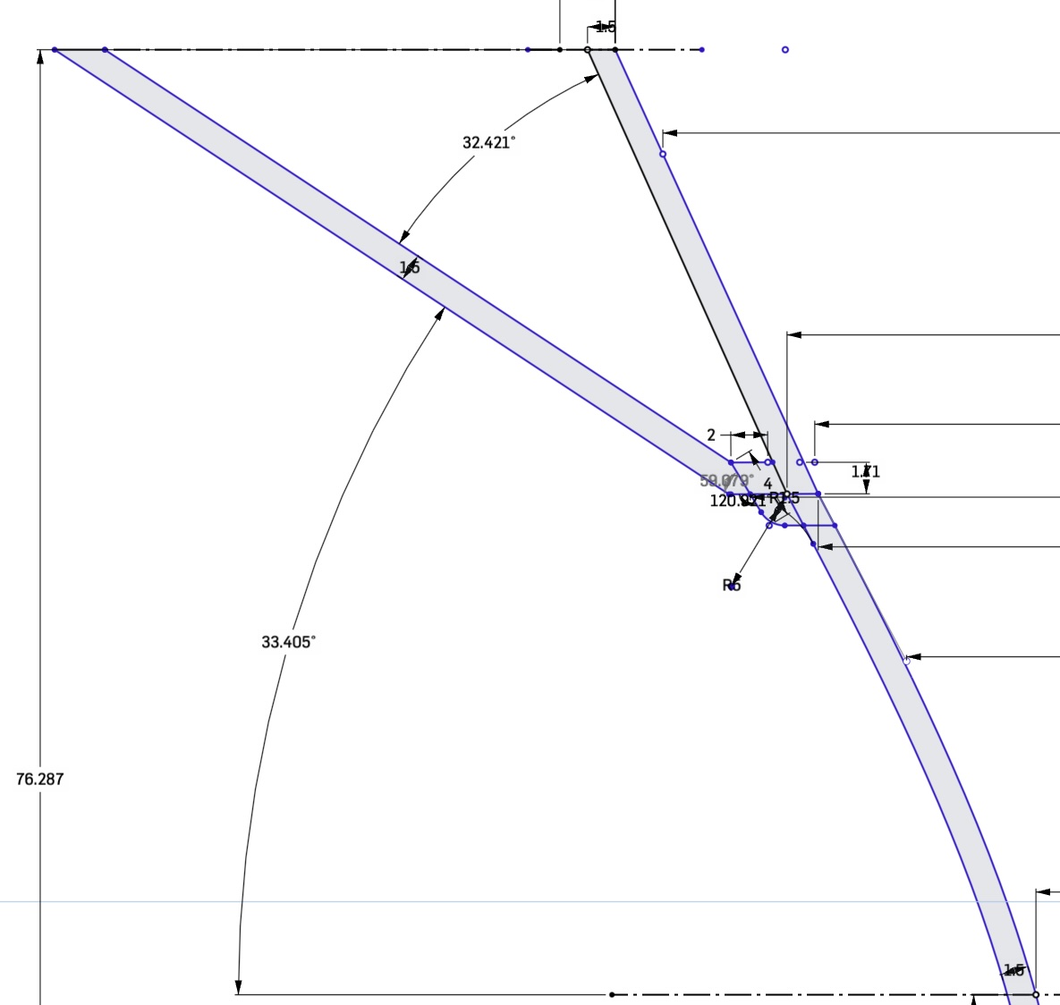
I’ve printed a container for avocado stones with a water reservoir at the top (though I printed the wrong one – the upper reservoir is useless as there’s no connection to the lower one), as the water evaporates quickly, and the upper part of the container has a platform that requires a lot of support material.
I’ve started modifying it so that there are practically no horizontal flat surfaces left.
The steepest wall is at 33 degrees. Can it be printed without support?