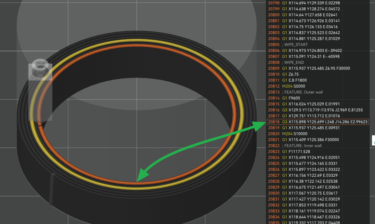
In trying to diagnose why a mostly cylindrical print sounded smooth on some perimeter loops, and sounded very grunty on others, I noticed the arc fitting is only being applied to external perimeters, and even perfectly circular internal perimeters are still interpolated with G1 moves. This is true on both classic and arachne engines.
Why not fit arcs everywhere (besides slicing time)? At least give us the option so the printer runs more smoothly and more quietly. Plus, internal perimeter artifacts will print through to external perimeters.
Are you using a primitive to diagnose or is this an STL file? Have you tried using a STEP file if available?
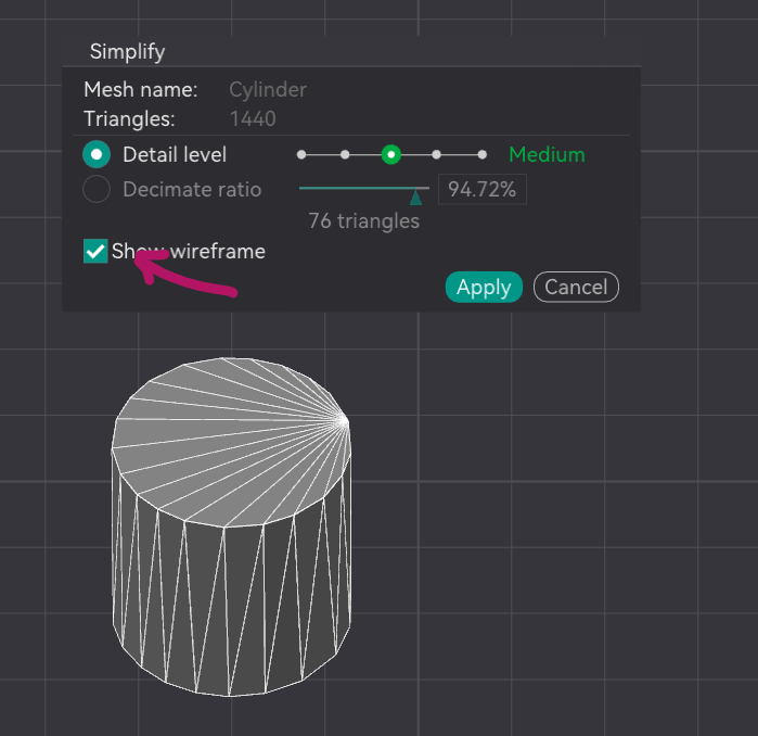
I only ask because a primitive will have native geometric calculations allowing for smoother curves and arcs. What might help is if you could show us a screen capture of the object under the simplify object menu with wireframe checked. This would display the underlying mesh and would rule out any possible glitches in the model rendering within the slicer algorithm. In the example below, this is a base cylinder primitive and you can see where the mesh is uniform as well as where the seam is.
Here’s what I found in my quest for hole accuracy which may be related here. When I imported an STL file, I was at the mercy of whatever software created that mesh. What I learned is that there are a lot of variations in output. Since then, whenever I have the ability to use a STEP file, the mathematical transforms are far more accurate within the slicer.
A good test would be to get an a circular object in both a STEP and STL format. Ideally if you have access to CAD, create this file yourself so that you can trust exactly what input you dialed into the Object. I found that was the only way I could ensure that if let’s say I was creating a 100mm x 20mm x 5mm rectangle with a 10mm hole, I knew precisely what was input and could therefore create precise measurements to later be used in my X-Y dimension adjustments for each filament. Admittedly this is a bit OCD but in my case I am trying to push the limit of printed dimensional accuracy.
This has me intrigued. I just tried to duplicate what you did. I’m not following. Do you mind sharing the steps you created before you did this screen capture?
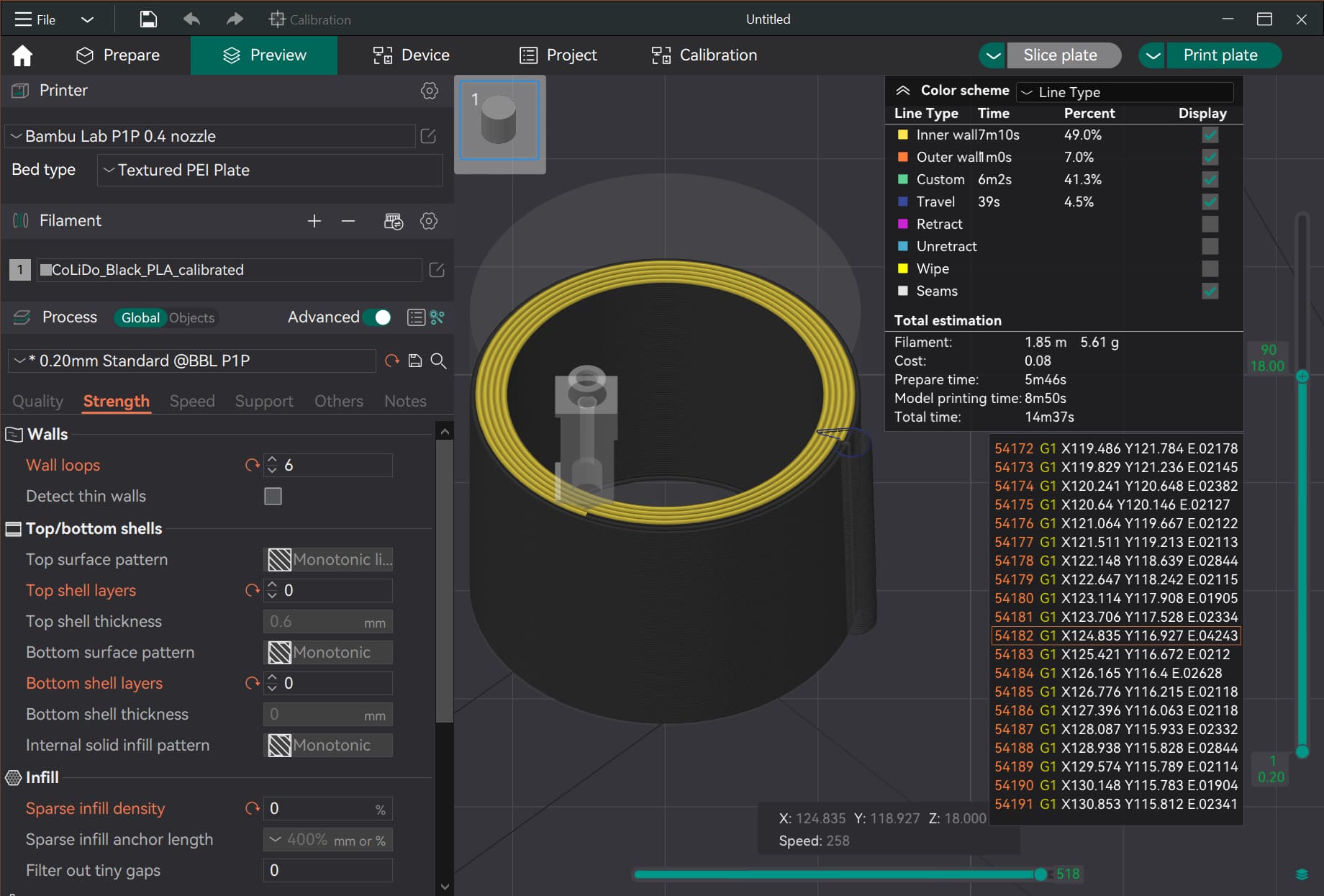
In the example previously, I changed the walls to 5 and bottom and top layer to 0 and infill to 0. But I’m obviously missing a step here to get to the analysis you’re trying. Admittedly, this is a new avenue of slicer understanding for me so please be patient.
If you absolutely need better curves, here’s what comes to mind me when creating objects in CAD software.
First I create objects with lower facet counts. As much as I need to create the object. If I want it to have better curves, I increase the number of facets. I can also do that later. The software automatically creates the facets to create better curves. In addition, more facets are simply created for a curve. Theoretically, I can repeat this as many times as I want and the curves will get better and better. Once you reach a certain facet size, you’ll see virtually no difference in the slicer because the resolution is the same or higher than that of the printer itself.
The thing with the STEP files is of course a good idea @Olias, some modern programs allow you to describe real curves instead of building them up from facets.
I have used both primitives and STL files (my own). The issue happens with both.
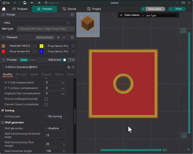
As for STP vs STL, IMO the STP implementation in BS is terrible. Here is a comparison of the same model brought in as an STP (left) and an STL (right) :
It sure looks like you are demonstrating the issue from your screenshot. You have perfectly circular walls, and the gcode is all G1 (linear) print moves.
Your screengrab really highlights the mesh artifacts perfectly.
Have you tried the new Orca Beta 1.8 to see if it produces better results. I ask because they recently included the Polyholes feature from SuperSlicer that converts holes into polygons. I don’t quite understand the math behind it but it’s supposed to leverage the printers innate ability to better perform straight movements while the filament naturally wants to travel along an arc when the polygon reaches a turn. I haven’t test it yet but the result is to perform much smother and precise circles.