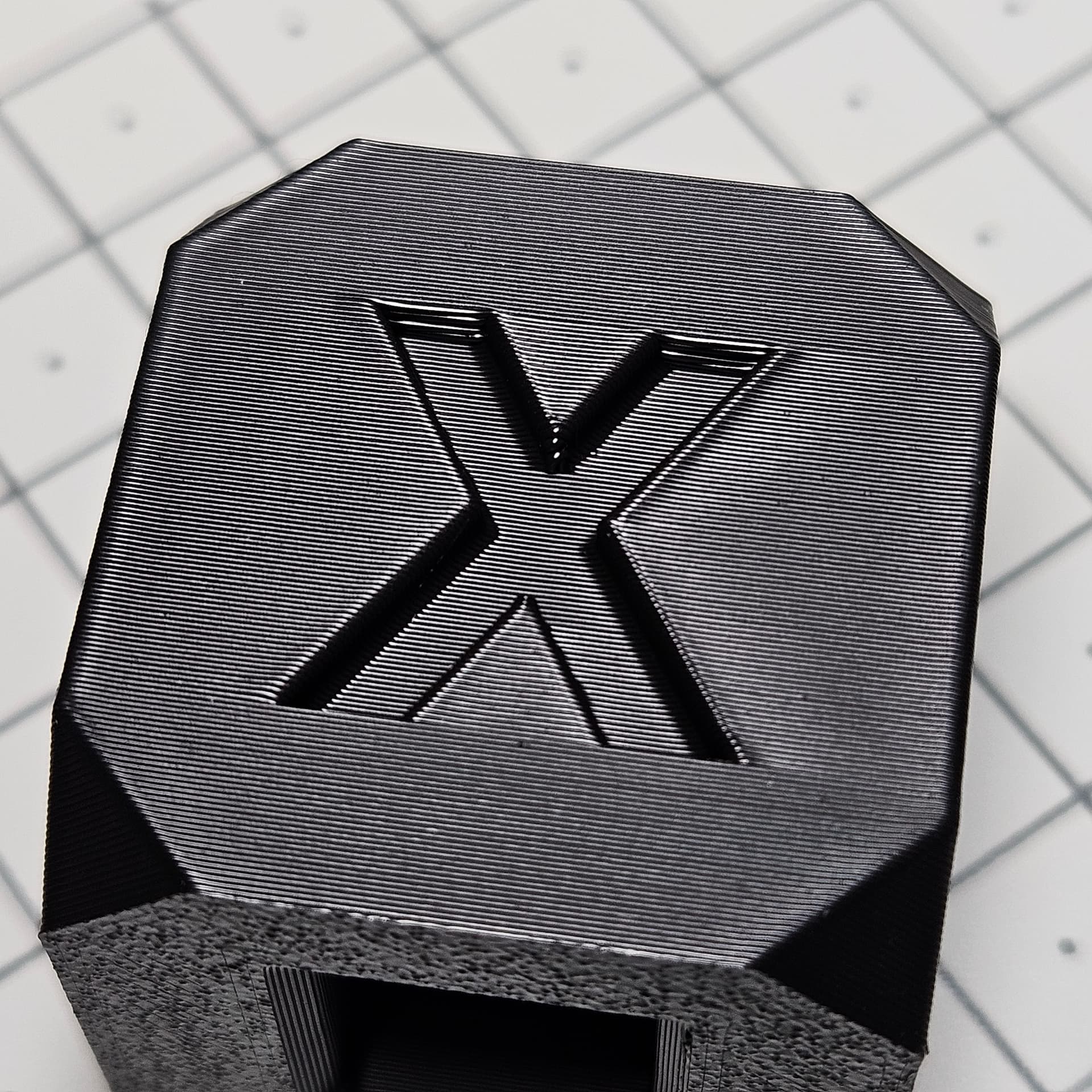
Post the speed view from the slicer - it would help understand what speed the external perimeters are actually printing at, as the filament cooling options in the slicer can affect the print speed. Also a shot with a top down lighting would be better to evaluate artefacts - side light shots tend to hide them.
Finally in the shot above you can see the corners being inconsistent. This may be due to motor movement because of the dampers. Would be good to understand seam placement in that model and whether these artefacts happen because of the seam jumping around or because of stepper wobble.
this are mine cubes with 200 m/s speed.
cube on right was with 0,97 flow rate, and left one with 0,96. But from calibration flow should be 0.97.
One more difference: left one has outer/inner, and right one inner/outer.
I agree that it could be a bit better, but there is so many factors having an impact on the print quality that’s too much time consuming to try to find the perfect settings for each and every spool.
Like in slicers, so many settings, difficult to master them all, and to spend hours to play with them for each and every print.
Some printers produce better results than others, so there is also some lucky owners having a better built one than others.
My own X1C as nearly 4000h, so I don’t complain too much about quality, especially since I changed the pulley (on a brand new X axis).
I’ve tried with another black filament (Sunlu PLA+ instead of Eryone PLA+), different result :
Man, this thing was not designed with user serviceability in mind.
It’s taken me 2 hours to strip the X axis off the machine and then another hour to replace the pulleys with toothed items.
Taking a break for dinner and then it’s reassembly time.
How did you figure out where to drill and what size drill bit did you use?
I’m thinking I’d locate the pulley rod on one side and lining it up with a drill press, add stops, and flipping it around to drill through the other side.
I eyeballed it. Used a 5mm bit. I had to gring a bit of the carbon rod down to allow the shaft to come out. Looks like the rods are glued in after the shaft is installed.
This speed would normally be above the peak VFA speed - can you do a test where the outer wall is printed at 120-140mm/s where the VFA is the worst? The results are promising so far, but testing the worst case scenario is what I think is really needed to conclusively say this is fixed.
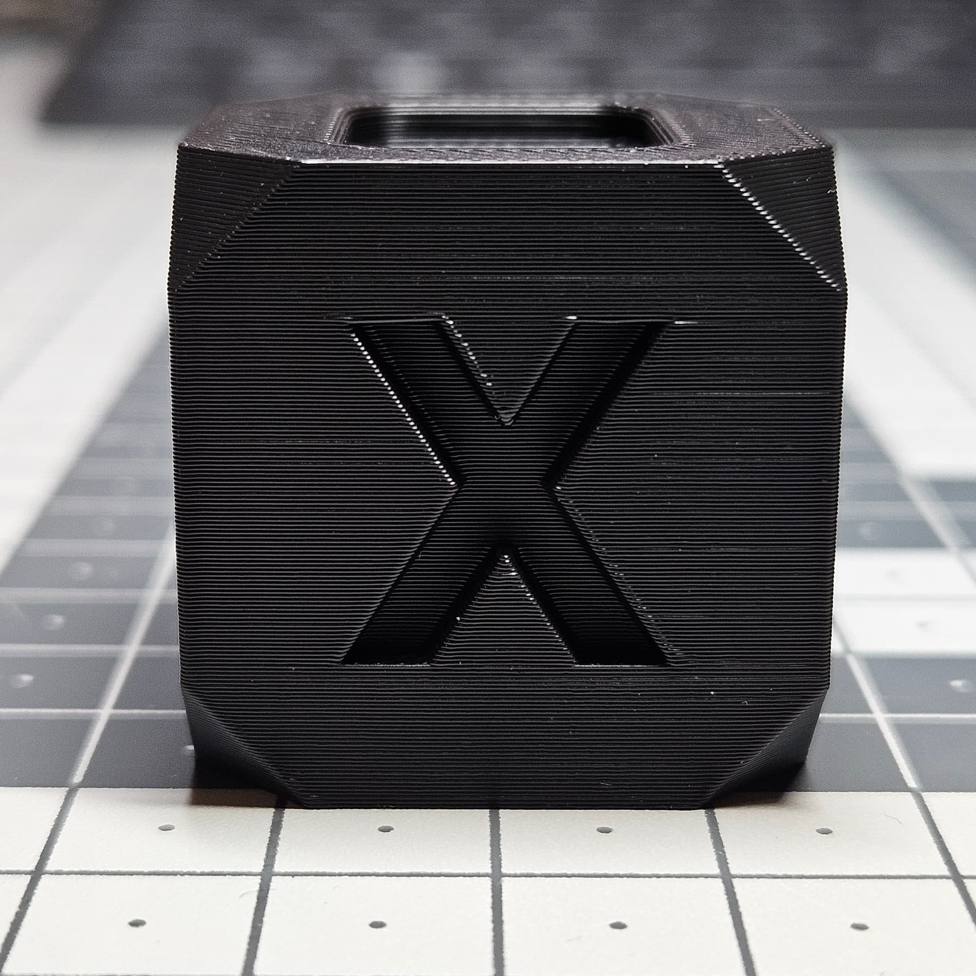
I ran the same print at 130mm/sec out wall speed. It looked identical to the one on the left of the picture above that was printed at 250mm/sec. Very slight VFA but barely noticable.
No, the other way around. Left is with toothed. Right is stock.
The light is hitting at the same angle. You don’t see the pattern on the left one because it’s not there.
Here you go. A part I just printed off. It was oriented on the plate as per the screenshot. This would have looked terrible on the rear as my printer was before.
I see you are working on a ball mount as well! (I’m making a custom application for my vehicle.) Some unsolicited advice, I learned from my designs that you can get a better print and stronger part by printing the ball and body separately. That way you aren’t compromising ideal print positioning for the multiple geometries. Also, by adding a bolt down the middle of the ball to secure it to the body, you gain added strength from the metal reenforcing the most vulnerable section. It also allows you to swap out different mount options with the same base plate or inn the worst case scenario, it breaks. Great work! Can’t wait to see it installed.
Thanks. The ball has an M4 bolt down the middle for strength. I’ll probably not use a ball mount in the final item. I put it there just to gauge angles when it’s in the car. I’d rather have the thing I’m mounting to be solid.