I ran the test from maker world “bridge test no supports” and had some interesting results.
The 1.5 flow rate for bridges looked amazing, but a little higher up there was a second bridge above the gyroid infill) that sagged badly, thus causing top surface issues. Any idea why the two bridges are different?
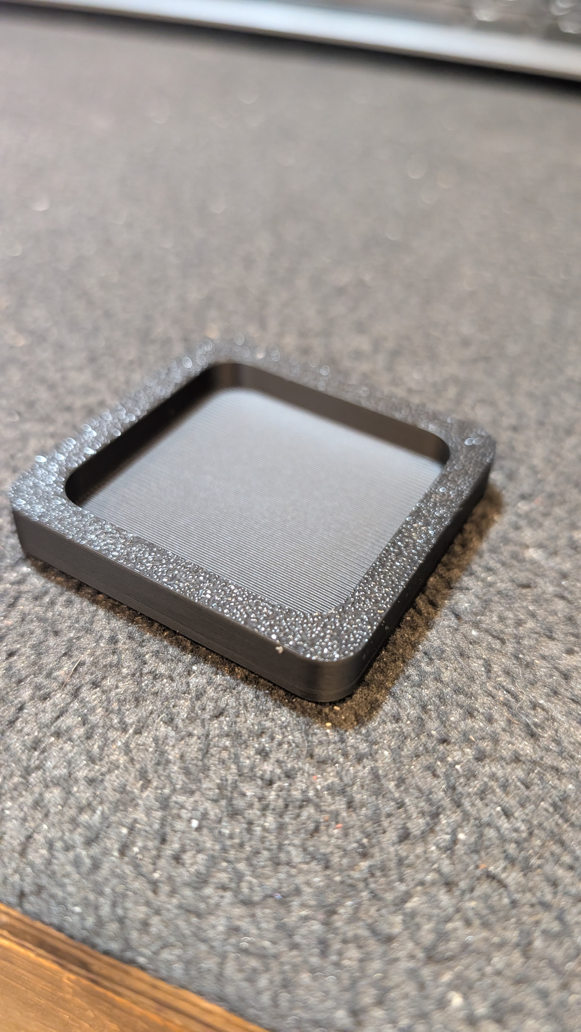
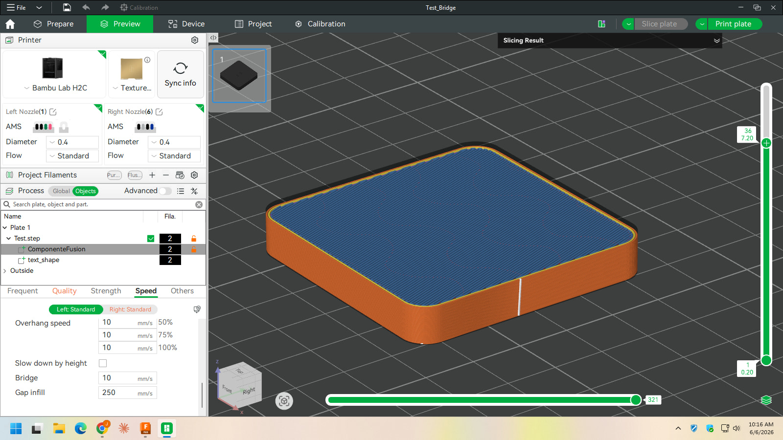
here’s some pics of the actual model for reference…
and this is the resulting top surface i believe due to the second bridge sagging
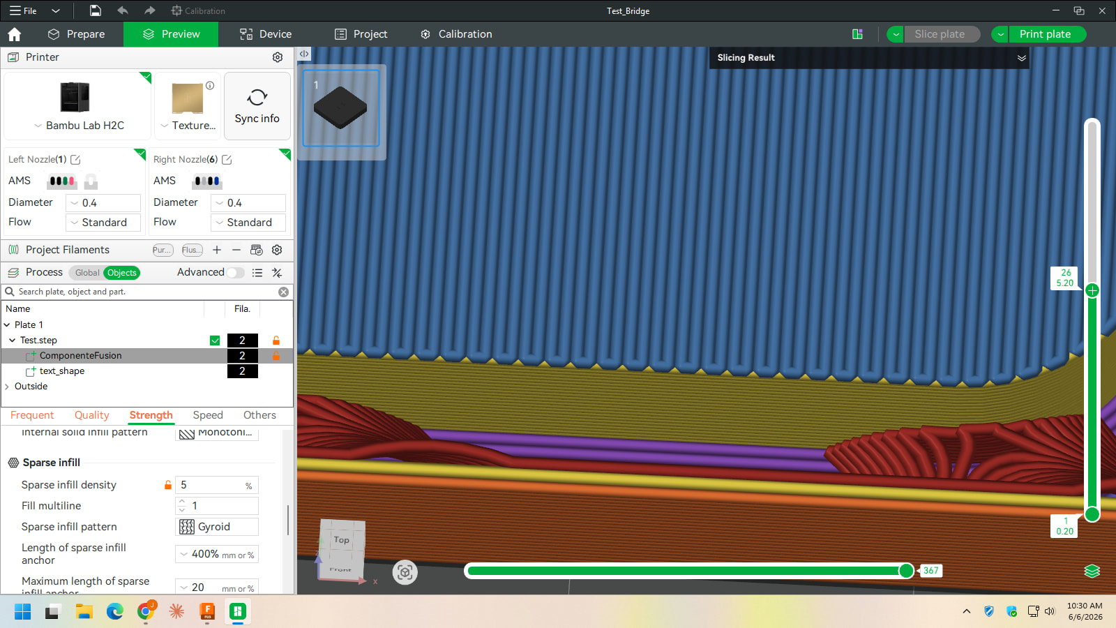
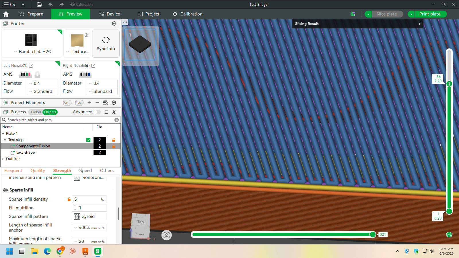
I discovered something… on the first bridge the lines are tight together. on the second one they are spaced apart. both pics are same zoom level. ideas?
It probably depends on how the slicer figures part cooling between the 2 tests. Also, depending on the type of filament used, you might be asking a lot to run that sort of test.
The 1st test looks much shorter of a bridge to gap vs he second curved path up higher which makes sense for sagging.
I’d force the part fan 100% past a certain layer of the bridges and see if that doesn’t stop it.
With ABS.., for instance, you could darn near run accross that entire model with no supports at all with the proper cooling. It hardens that quickly.
it’s actually just 1 test, same part, same settings. i’m just using PLA and my fan speed is set to 100% the whole time… I would imagine the top bridge would actually even be better than the lower bridge because it has the gyroid supports underneath (as in my one pic, you can see them).
I’m confused.
It looks like your first image you are only bridging the outer edges.
Then the next image it looks like you are bridging across the entire model.
I thought that’s the 2 comparisons you were making.
And the raised wavy sections that you asked about (the bridging across the entire model) looks much further between each section than the outer section of the 1st bridge.
So I don’t understand how it’s the same on both.
no, it’s all the same part… there are 2 bridges in the part, layer 26 and layer 36 (you can see the layers on the right layer bar in the screenshots)