I’m surprised to find that there are no ‘self-contained’ (robot-oriented) options for CyberBrick. I get that RC toys are the primary focus. But I somehow expected that there would be options for other uses too.
All we would need is a shield board that has a mixture of both inputs and motor/servo outputs.
Am I missing something, or do I need to look at an Arduino Nano or some other type of nano-controller? This seems like a missed opportunity for models that only need local logic.
Thank you for the reply. What controller / motor driver system are you using?
My particular use case is pretty simple. I have a single motor that I need to stop at certain gear positions. So 1 motor output, an input for button to start the cycle, an input for a button or linear potentiometer to stop the cycle, and an input for a rotary potentiometer or rotary switch for timing control. That is 3 GPIO inputs and one motor driver output and very simple logic overall.
If you can do it with an Arduino Nano, you can do it with the ESP32 in the cyberbrick.
You can even do it with the ESP32 using the Arduino IDE if that’s what you’re used to.
Just have to repartition the memory map to blow away the Python interpreter that’s there now and you’ll have access to the full feature set of the SoC. The ESP32-S3 has BT and WiFi support, and its Xtensa processors have “vector instructions” for AI use cases that’d be applicable for robotic use.
You could even use ESP_WIFI-MESH (or painlessMesh, which is what I use) to easily connect multiple units on a private adhoc network for communicating and coordinated actions, without have to deal with any of the complexities of typical network stacks.
If I go this route, do you think I would be able to reconfigure the GPIO ports that connect to the CB receiver shield in such a way to turn the LED outputs into usable inputs? Or is that part of the hard wiring of the shield itself?
Since you are talking about leaving the stock Cyberbrick environment, you have a whole world of options that are actually intended for mixed I/O, with all sorts of peripherals embedded in the board or able to be used through standard port configurations and protocols with ready-to-go libraries to use them all.
Have you considered a standard hobby servo for the positioning you want to do? It’s fire and forget but they have pretty good accuracy and repeatability all on their own. Also very easy to add to a number of microcontrollers.
Adafruit has a bunch of microcontroller boards with families based on various chips. Various boards have temperature, humidity, display capability, sound, neopixel drivers, etc.
As long as you are breaking the mold, you have lots of options open to you. I’m a big fan of Adafruit’s “Feather” line and the boards built around the RP2040 and similar.
I’m assuming the LED is wired to an open-collector output, so there’s a connection from V+ through a current limiting resistor to the LED, and then from the LED to the ESP32. If so, remove the LED and the cathode connection pad should go right to the ESP32. The anode pad will still be connected to V+ through a resistor, so you can check the pads with a voltmeter with the board powered and the one with the resistor should be obvious. Or with the board powered off, an ohmmeter from V+ to the pads should show which has the resistor connection. The resistor should be on the order of a few hundred Ohms.
And while I’m not 100% certain, I’m pretty sure that any pin that can be configured as an output can be configured as an input. So you you don’t want/need the LEDs, then I think what you want to do ought to be doable.
What they look like electrically has not been documented as far as I know.
No mystery. Addressable LEDs. They are powered separately, not through the connection to the SoC like a normal LED. Instead of sourcing or sinking current to light the LED, the SoC provides a serial data stream that tells a LED to turn on/off and if it’s colored, what color and brightness. They are often connected in series, and you can control each LED in the series independently with the single data stream.
Many libraries for the Arduino environment that will drive these devices. Easy peasy.
It’s still just a digital output, it can be retasked for an input or a different type of output. Nothing special about these LEDs or the requirements to make them work. Any SoC that can do serial data output can drive them.
I use these addressable LEDs all the time. I’d post a short video of an example, except linking to YT seems to be broken at the moment…
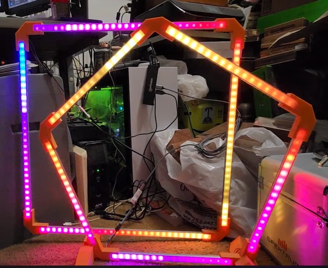
Here’s a still image. Imagine the colors of all those LEDs constantly shifting around, and changing the pattern of the animation. You can see some of the LEDs are dimmer and some are brighter, which is part of the pattern that propagates around the entire ring. These are race gates for indoor drone racing.
I don’t have a Cyberbrick, so I don’t know anything about the specific circuit design BL used. But I have been using ESP32s in various projects for years. So while I don’t know what BL actually did, I do know what an ESP32 can be made to do. No mystery to how an ESP32 can be used to drive a single LED directly (what I originally assumed the brick was doing), or drive one or more addressable LEDs. The connection to the ESP32 works differently for a single LED or an addressable LED, but physically, they both connect the same way, requiring a single digital output to drive the LEDs. And that pin on the SoC can be reconfigured just like any other digital IO pin on an ESP32. Easy Peasy.
It may not be totally correct to talk about anodes and cathodes with neopixels but they still have LEDs with anodes and cathodes. The terminals are generally just marked with a + or - though.
Neopixels have some sophisticated circuitry in them. System on a chip kind of thing. What neopixels really have are power rails and daisy-chained serial ports and shift registers. There’s red, green, and blue LEDs with brightness controlled on each by PWM. You don’t connect directly to the LEDs but one rail may so in a way it could still be a cathode or anode.
While that’s complex sounding they are really easy to use. In many ways easier to use than discrete LEDs. With microcontrollers, it’s frequently easier to use neopixels and you get RGB/brightness capability. And you’re only driving a digital input so pin loading usually isn’t an issue. With LEDs designers should verify their chip can source or sink the current needed to light them.
I doubt the pinouts are the same (haven’t even checked but maybe?) but Adafruit has similar boards based on the Expressif ESP32 chip.
There’s lots of sample code and examples, schematics, etc at the Adafruit website. If you are interested, just search for ESP32 and QT Py. Those are small format boards very similar to the Cyberbrick’s.
Depends on what you’re looking for if that’s any use, though.
I am interested in if there is any buffer circuitry, like, open collector output with a BJT or mosfet to improve current driving capacity at “IO pin” or so. If it is the same as xiao boards, then it is just bare IO pin break out from the micro. I understand it isn’t open source. I can reverse engineer the board but just too lazy to do it.
I bought a cyberbrick kit because I was curious mostly. I haven’t had a plan to do anything with it yet. It probably will sit in a drawer collecting dust.
I simply don’t like ESP32 since it cannot do DMA stuffs unlike STM32. Anyway, cyberbrick users probably don’t need and don’t understand low level stuffs like DMA, so ESP32 is just fine for cyberbrick toys.
It’s a tough problem. Even the simple chips can be confusing for those who don’t have much or any experience with these kinds of things. It takes a while to really get a good mental picture of what these chips can do even if people have experience with similar stuff.
I was just looking at the ESP32 reference and it looks to have some DMA capability but no idea how it compares to an STM:
ESP32-S3 has a general-purpose DMA controller (GDMA) with five independent channels for transmitting and another five independent channels for receiving. These ten channels are shared by peripherals that have DMA feature, and support dynamic priority. The DMA controller controls data transfer using linked lists. It allows peripheral-to-memory and memory-to-memory data transfer at a high speed. All channels can access internal and external RAM. The ten peripherals on ESP32-S3 with DMA feature are SPI2, SPI3, UHCI0, I2S0, I2S1, LCD/CAM, AES, SHA, ADC, and RMT.
I’m new to the ESP32 stuff but if I’m reading it right, there’s also a big switch matrix in them that lets designers use any peripheral on any I/O pin. If I read that right it’s kind of mind blowing. It used to be pins were set in function and if you wanted access to an ADC or I2S function you had to wire to that pin. It’s wild if that requirement is gone now.
The other nice thing is that Digikey/Mouser are distributors so boards are easy to get in a very timely manner at a very reasonable price. I often use them to top up an order for free shipping.
Amazon and Digikey also sell Adafruit stuff which makes them easier to get for some as well. Probably other outlets too.
Anyway, with that switch matrix feature I bet they are all pretty interchangeable with that chip. I haven’t tried it but I bet the Cyberbrick stuff has way more capability than is used.
I haven’t used any of the Cyberbrick dev tools but bet pretty much any favorite dev environment could be used to allow more capabilities in the Cyberbrick stuff. But that turns any projects based on non-Cyberbrick tools into things users will probably have harder times setting up.
Would be cool to see some projects that do that though. Could be a way to get more flexibility in the Cyberbrick dev tools. But added complexity also leaves some behind.
For arduino framework, it was likely none available. Using espressif sdk, it is possible for those peripherals as you said, but not for UART.
The story is:
My job a while ago was to use esp32c3 as UART to BLE in transparent mode. It was an attempt to cut cost from using RN4871 and mostly to mitigate the chip shortage problem during covid-19. I spent about 2 months experiment and then realized there is no DMA for UART. Basically, UART hardware must be controlled in software. So that during listening for or transmitting BLE message, it misses data coming in over UART port, leaving corrupted data received on other end of BLE. It happened intermittently and the lack of proper debug makes it much difficult to solve the problem. I ended up increase the delay between data burst and wired up an extra pin to the main micro to work like hardware UART flow control, but all in software in both main micro and esp32.
We were panic when RN4871 was out of stock, and we had to use RN4871U with older firmware that does not support long MTU unlike RN4871. At the time, I was considering using WCH CH9143 instead of a “generic” wifi/ble and microcontroller combo like esp32c3. But my boss insisted on ESP32, so that’s that.
I’ve been trying to figure out if cyberbrick might work for my project, but reading through this thread makes me think it’s not a good fit… I have one physical location for inputs, but two physical locations for servos/motors/LEDs… one of which is adjacent to the inputs.
If I could pair one transmitter shell to two receiver shells and communicate with them simultaneously, that might work, but I can’t find anywhere saying that’s possible. Anyone know?
ESP-NOW uses 2.4GHz radio hardware of ESP32. Unlike 802.11b/g/n protocols (aka wifi 2.4GHz), esp-now doesn’t require a router that acts as access point. I believe CyberBrick is using the same esp-now.