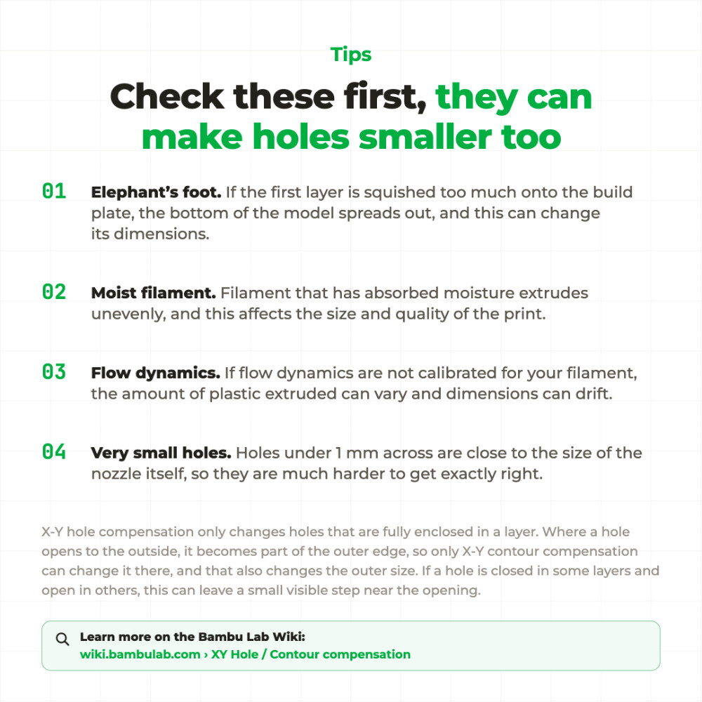
Learn more about X-Y hole compensation from the Bambu Wiki: XY Hole / Contour compensation | Bambu Lab Wiki
Learn more about X-Y hole compensation from the Bambu Wiki: XY Hole / Contour compensation | Bambu Lab Wiki
I find hole compensation quite useless the way it currently is implemented in most slicers including BambuStudio. Thst is mainly for two reasons:
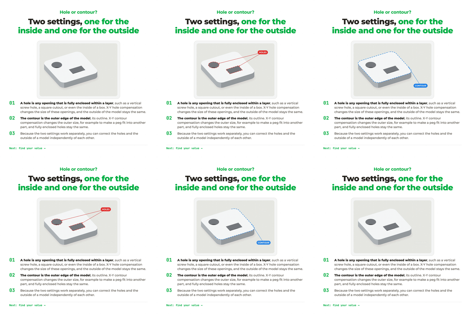
Hole compensation only affects closed shapes. A circular hole with a slit that connects it to the outer contour shrinks exactly the same as a closed hole but is not corrected by hole compensation XY.
How much a circular hole shrinks mainly depends on its diameter. E.g. a hole designed as 0.8mm might come out completely closed, it would need 0.4mm compensation. Very large holes, e.g. 100mm diameter almost don’t shrink at all, maybe they would need 0.02mm compensation. those numbers are taken from an actual test I did some time ago. And rectangular holes don’t need any compensation at all but are also changed by Hole compensation XY.
So the current implementation uses the completely wrong criteria to decide which walls should be modified how much.
I ressort to compensating shrinking of holes in CAD instead. For my most used filament, I have created test prints with different hole sizes that I have accurately measured and put into a table. So when I need a hole that is exactly 1.5mm with e.g. PLA basic. I look up in the table which designed diameter resulted in a 1.5mm actual hole and use that instead.
A more sophisticated hole compensation would be highly welcome that actually works!
I agree. It works for simple things only. A more complete solution would be a “Paint on” correction, like how color painting works. Mark these surfaces, they will offset + or - by 0.xxmm
Sometimes there are holes of different sizes or even different kinds of holes (round vs square) on the same model. It will be great if users can mark which hole to apply which compensation.
As mentioned in a post above, it will be nice if users can mark a semi hole and ask the slicer to treat it as a hole. I recently ran into a situation in which such a feature would have been very helpful.
One part of the shrinkage happens before the slicer, in the STL itself. A circle in an STL is a polygon with its corners on the circle, so its flat sides sit inside it. A 5 mm hole exported with 16 segments is only about 4.90 mm across the flats. With 48 segments it’s about 4.99 mm.
That’s one reason a single compensation value doesn’t fit every hole, as Alex_vG said: the polygon error depends on how each hole was exported, and it adds to the shrinkage from printing.
Two ways to take it out of the equation:
There was another thread going around about how holes tend to print with a diameter that is 0.2mm smaller than designed — a 3D printing characteristic that many designers are aware of and compensate for in their designs.
From experimentation by trial and error I have come to a few design rules-of-thumb that allow for variations in the properties of filaments and the geometry of the parts and still work as described.
Sometimes the numbers need a little tweaking but these are what I start with and have had the most success with.
I think that 0.2mm rule only works for a limited range of diameters. When you try that rule on a 1.5mm hole, I’m sure, the necessary offset is considerably more than 0.2mm. And on very large diameters, you can reduce the offset.
That was one of my points: shrinking and needed correction of round holes is not a single value but depends on the nominal diameter. the smaller the hole, the more it shrinks in terms of absolute offset needed.
The 0.2mm diameter under sizing of holes is consistent in the holes I have tested from 2mm to 200mm diameter holes. Rectangular openings exhibit the same 0.2mm offset. It is somewhat related to how on milling machines the minimum possible inside radius is equal to the radius of the cutting tool. In this case the nozzle can be seen as a tool with 0.4mm diameter. If it follows a line it will print 0.2mm on each side of the line. Apparently this is what happens when printing holes in 3D printed objects. From what I hear, it has been a characteristic of 3D printers since the beginning. But then, g-code and slicers have their origins in the lithography (thus the term stereo lithography or STL) that was being used to plot printed circuit boards and integrated circuits. On PCBs the holes are drilled out, rendering the under sizing of the ID meaningless.
I have discovered that even though 3D printers aren’t always the most accurate machines, they are highly consistent and repeatable. If one prints all the parts on the same printer, or even the same line of printers, if all the parts shrink at the same rate, the gaps adjust with the shrinkage at the same rate as everything else, and everything fits fine. Even though my experience is that shrinkage with PLA and PETG tends to be insignificant.
Oh, that’s interesting. How did you test the needed offset?
I did a test series too from 0.6 to 5mm and a few larger diameters. I used two different materials and the shrinkage wasn’t the same across diameters and it also was different for PLA and PETG.
I even bought a set of test cylinders from 0.3 to 5mm in 0.05 mm increments, because I find it really difficult to accurately measure the diameter of a hole.
But well possible that my test was flawed. Maybe it is as simple as a bad flow rate calibration? With your input, I feel motivated to repeat the test again. Flow tests based on Archimedean chords allow much better calibration than when I did the test the first time.
What doesn’t add up for me: a rectangular hole shouldn’t need any offset. but a hole with 4 very slightly curved walls should behave the same as a big cylindrical hole and need an offset of 0.2mm. So somewhere there has to be a transition.
Ok, that definitely isn’t the case for me. Then I would argue that your printer is overextruding, e.g.flow rate is too high for the filament.
If that was the case, one would expect the diameter 0.4mm too small, because the walls on opposing sides of the wall would both be inset by 0.2mm. Or in other words, one would expect the radius to be 0.2mm toi small, not the diameter.
And slicers consider the width of the bead. They don’t set the lines exactly on the border of the object but inward by 1/2 the line width so that the edge of the bead is exactly on the edge of the object.
Also all slicers don’t print beads exactly the size of the nozzle but typically a bit wider. E.g. BambuStudio uses by default 0.42mm outer walls and top, 0.45mm inner walls and infill and even 0.5mm first layer for a 0.4mm nozzle. I have already printed 0.8mm wall lines with a 0.4mm nozzle and the outer dimensions matched exactly the design.
There is an effect that only affects concave walls like in round holes that I heard the name “rubber band effect” for. Assume you want to print a 5mm hole and your printer lays down the inner bead perfectly accurate, so that the inner edge of the beads have an exact diameter of 5mm. The still liquid filament cools down and shrinks slightly at the same time. As it is anchored to the layer below it builds up tension along the circumference. The only direction it can escape to is the inside of the hole where no other material is in the way. So it slightly moves into the hole, reducing the inner diameter. The smaller the hole, the stronger is the force pulling inwards.
When the amount of tension really depends on shrinkage of the material, then one would expect that filament that shrinks stronger also has more reduced hole sizes. That’s exactly what I observed. A nominal 1mm hole in PLA came out as 0.56mm. In PETG the same hole was only 0.28mm. (average of 4 measured holes). A 2mm hole became 1.74mm in PLA and 1.60mm in PETG. A 5mn hole became 4.83mm in PLA and 4.78mm in PETG. at that size, the difference is so small that my measurement uncertainty was probably larger than the difference but at no time did my measurements flip between the materials.
For me that confirms this theory, that I heard the first time 15 years ago.
I have printed out test plates where there are are a series of holes that increment in diameter, 0.1mm. I then measured them using numbered drill bit shafts and transfer punches as go/no-go gauges. The drill bits and transfer punches are are of a high precision. In my experience, 3D printed holes tend to print, on average, 0.2mm undersized. I have been designing objects with this rule of thumb in mind with great success.