I do see that I’m getting a message that its unable to perform a boolean mesh on the object and only the positive parts will be exported. I haven’t seen this come up in any video examples, so not sure what is going on with that message… but it’s only exporting the positive parts not the hole 
I’d love to help you but without the “clear” images I suggested it’s impossible to understand your design-intent. We can’t tell you how to achieve your objective if your objective is unclear.
Please reference the post earlier, otherwise we’ll be wasting time going back and forth trying to guess what you want the slicer to do. How many objects are we dealing with? Are they assemblies? How are you constructing them if they are? Is this model of your design or is it one you downloaded? What is the original file? Is it a STEP file or STL? You still didn’t post an image of the full model so it’s unclear what it looks like versus what you want it to look like.
The best thing is to upload the 3MF file. But as @BambuBanker stated, if you are a new user and did not go through the 10 minutes of tutorial, the anti-bot security measures of this forum’s software won’t allow you to upload.
Well I didn’t see, or get directed to any tutorial. And after searching I actually found a thread of new users saying they couldn’t find it either… sigh. I’ll keep making my minutes count up till I can post a picture. If you have a link to the tutorial, that would be appreciated. Thank you

ok, looks like I got my count up ;). So the model on the left is the model on the right that I exported as an STL. During the export I received the error about negative parts not being exported due to a boolean error. Is there a resolution to this? Or is this just limitations of the slicer at this moment?
OK. Your not expressing yourself clearly. I feel like I am forced to tease information out of you. If you want help, you have to be thorough and provide complete data, not partial sentences without context.
What model are you talking and how did you export it and to where? Your folder, your CAD? From the slicer? Details matter.
Again, what exactly did you do here? You’re using two terms that are not congruent. This statement “exporting”, “Negative Part”, “Boolean” do not normally coincide with exporting process. Again, it implies that you’re leaving out a whole lot of details. How many objects, what is there origin of these objects(STL, STEP, CAD???). What does the left side of the slicer process window look like with respect to models vs objects. Details matter!!!
If you want community help, you can’t expect folks to guess at what your questions are. Uploading the 3MF file “As it sits” when you get the error message, is critical as it freezes the state of your slicer the instance you experience the problem. Use “Save-AS” and save it to a new name to ensure that you’ve captured the conditions of errors when your uploading the 3MF file. Also, include a screengrab of the slicer with the error message so that the context is clear.
While we’re at it. What Slicer are you using, version? OS, etc.
There is no teasing needed. Here is a step by step, with pictures, of what I’m running into
software info:
Bambu Slicer 1.10.1.50
Windows 11
file source type: STL
- I imported an STL of the file I wanted to separate
- following the split command instruction I moved it to the layer line I want and then click add connectors in the drop down box.
- I size and place the plug position
- I flip the cut so I get the orientation of the connection I want and then confirm the connectors
- I perform the cut
- The cut is made, and one piece has the plug and the other has the hole (which is loaded as a negative object in the slicer now)
- I will right click on the part with the hole in it and select export as one STL
- If i select to mesh them before export i get the following error:
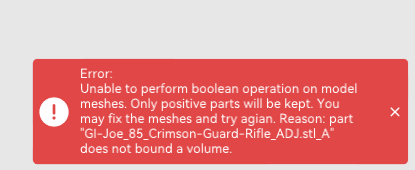
- When allowing it to proceed, i will attempt to reload the STL into the slicer again and there will be no hole.
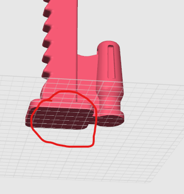

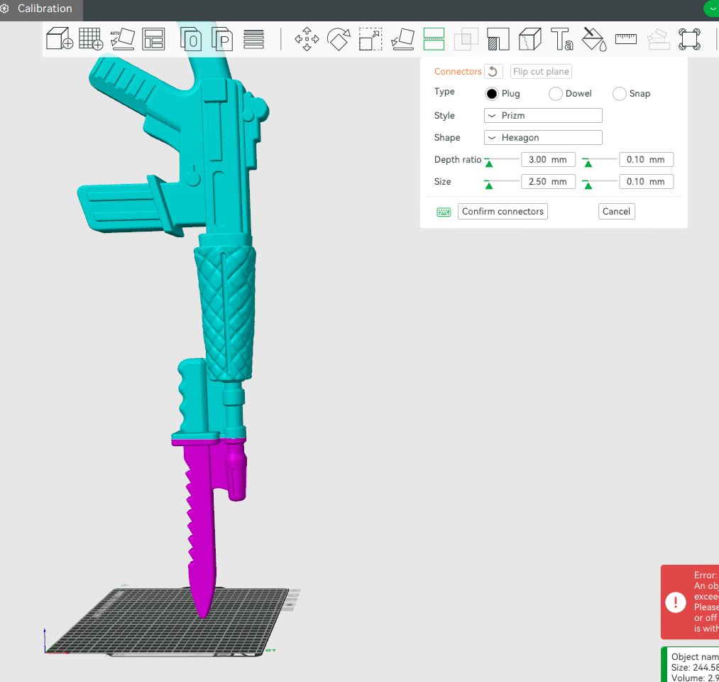
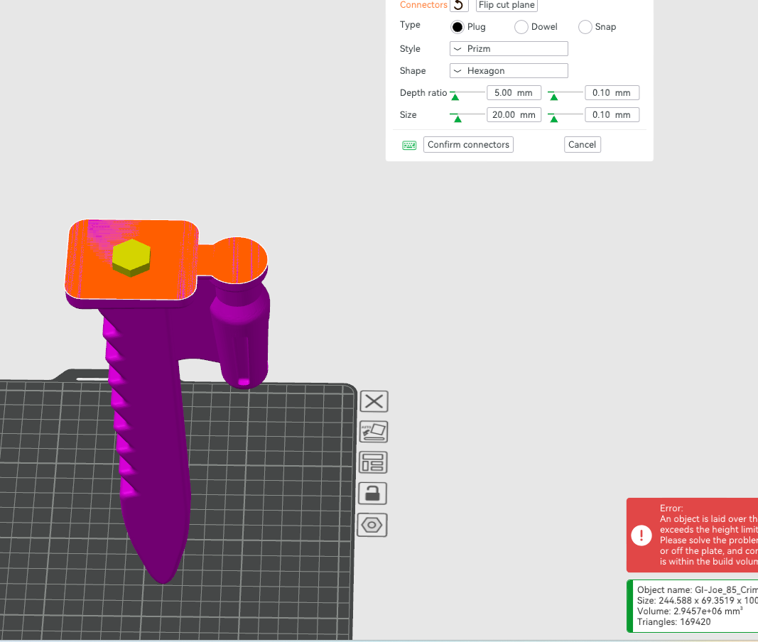


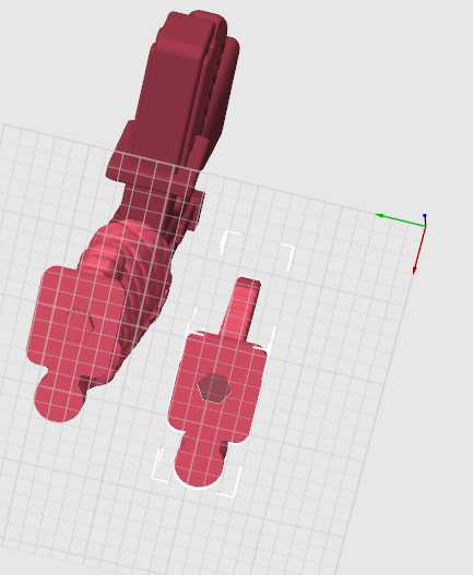

I hope this help clear things up. I am following video guides on Youtube as well as other step by step guides on the wiki…etc. but I am still running into this and I am looking for a reason why this is happening to see if it can be fixed in the slicer or if I need to go a different route.
Thanks for the clear step-by-step guide. This is very helpful.
I think I better understand what you’re attempting. However, it’s not entirely obvious what the slicer perceives these parts to be—they could be solids or part modifiers, which are very distinct.
If I may suggest, to eliminate potential model vs. slicer issues, you might want to test this approach using cube primitives. This will allow you to:
a) Validate your methodology.
b) Ensure that the slicer supports what you’re attempting.
c) Eliminates the possibility that the part mesh is non-manifold which would also create problems.
Here’s an example of what I am referring to. This is creating a plug using the cut tool. Ensure that you can get this to work first.

Then try to create multiple scenarios using different techniques. Again, ensuring that your methodology is correct.
Example 1: Negative part.


Example 2: Union of two solid parts that are part of an assembly.
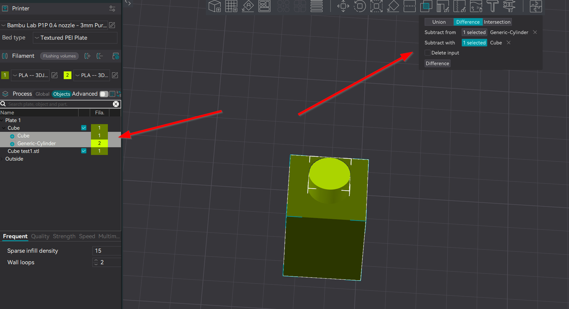
By creating a simplified example, you can then transfer that technique simply by substituting the models. If you can get the cube primitive to work, then you know your missing something.
Thanks for guidance. I found out the model that was given to me (STL) had hidden layers inside of it that was throwing the operation for a loop. I put the STL through a CAD program and re-exported a different STL and it looks to be operating correctly now
Thanks for closing the loop and letting us know of your success. It helps the community.
I suspected that the model might be the culprit but as I stated above, without specific access to the model, one can only guess. That’s why troubleshooting with primitives is such a valuable first step diagnostic measure. It is easy to replicate and really isolates the functions of the slicer. So in this way you are only diagnosing one thing at a time.
Thank you so much for this thread. I’ve spent ages trying to add connectors and wondering why the software wasn’t automatically adding them when I click “Perform cut”.
Did I really miss a bit in the user manual where it explains that you need to indicate where you want the connectors to be placed?