I have a multi part, multi material model, where I’ve drawn supports in CAD and it’s kind of required to do this. My issue is that I get an empty first layer error despite the fact that it’s not empty. There’s another model to print on top of. The slicer obviously doesn’t recognize the drawn support and thinks my model is in mid air.
Can I disable this setting and force it to print where I want it to?
I’ve tried adding the part to the (drawn) support, which removes the top layer for the support meaning the part will only print on to infill. I’ve tried generating supports, but the generated supports intersect other parts in the model.
If I import the model as one model with multiple parts, then the top surfaces disappear again on the supports that I’ve drawn.
TL;DR: No, there’s no magical setting to disable empty layer detection - asking for that is like asking for an “oxygen off” switch in an airplane seat.
That said, your post is missing key info. If you want meaningful help, provide as much context as possible. Reminder: Bambu employees rarely participate in this forum - this is a peer-to-peer group.
Here’s what would help:
What CAD system are you using? The answer will encourage fellow community members experienced in your system to chime in.
What file format did you export (STL, STEP, OBJ, 3MF, etc.)? This is a big thing to leave out, it will affect the trajectory of possible solutions.
Screenshots of the model in both Prepare and Preview views. Best of all, upload the 3MF file if you can - makes troubleshooting far easier.
Barring that, we’re guessing. Here are two likely causes of empty layers:
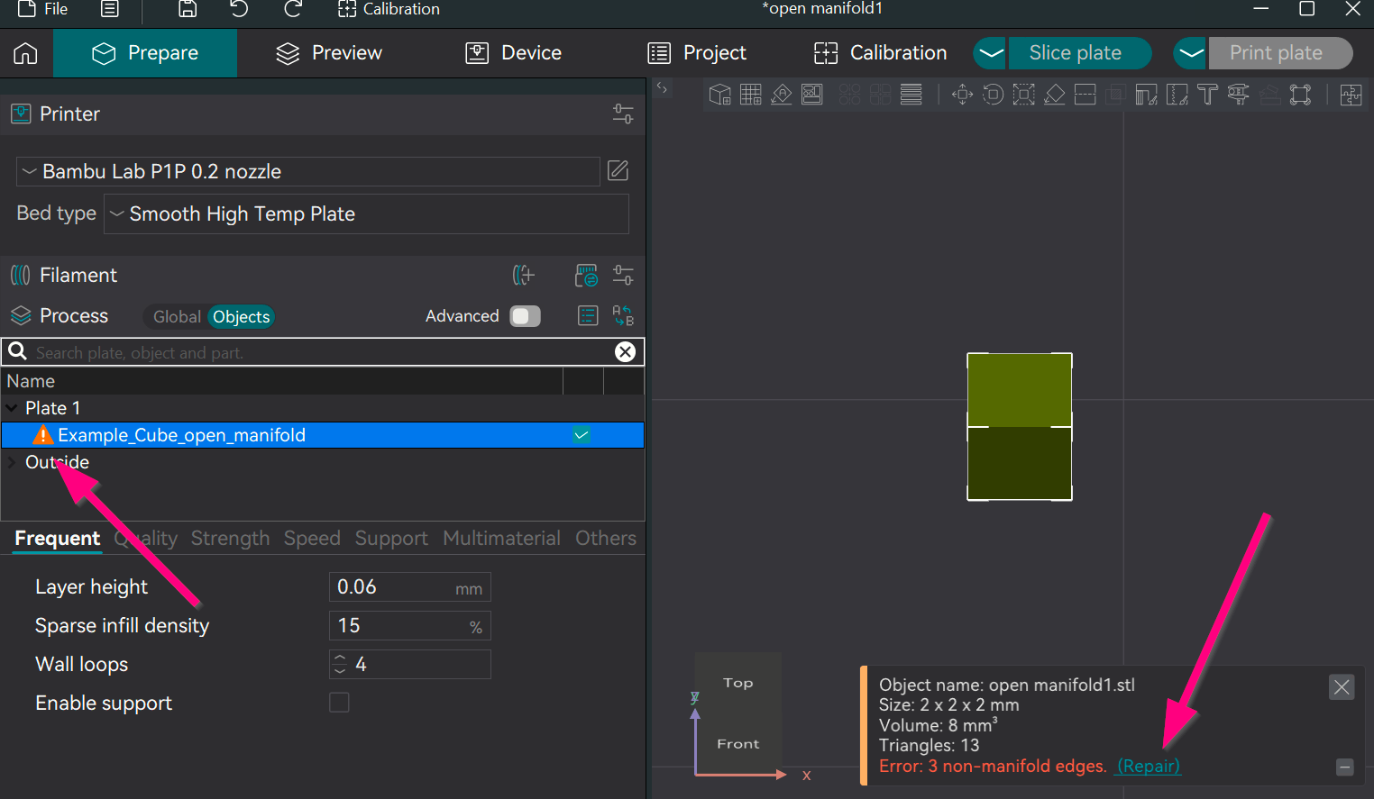
1. Open Manifold / Mesh Errors
Mesh-based formats (STL/OBJ) can have holes or geometry issues. When this happens, the slicer tries to “heal” it. If it guesses wrong, you could get empty layers.
Inside the model: The model may be defective from CAD export. There is no other way but to try another file format such as STEP or go back in and fix your CAD model.
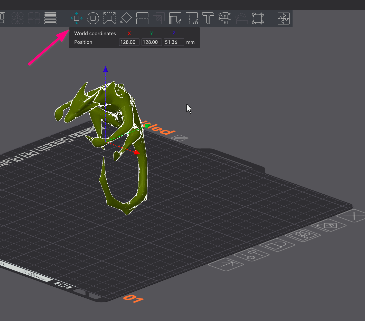
At the base: Try lowering the model slightly to seat below the build plate using the Move tool. Even a subpixel gap can trigger errors.
Possible other fixes:
Avoid STL/OBJ/3MF if your CAD system can export STEP. STEP uses math-based surfaces, not vertices - infinitely scalable, far more reliable.
If you can’t export to STEP, you’re likely not using a true CAD tool. Blender, for example, is mesh-based - not parametric CAD. Some Blender extensions add limited parametric tools, but it’s still not a proper CAD environment.
Assuming the support structure is correctly drawn to generate a mesh…
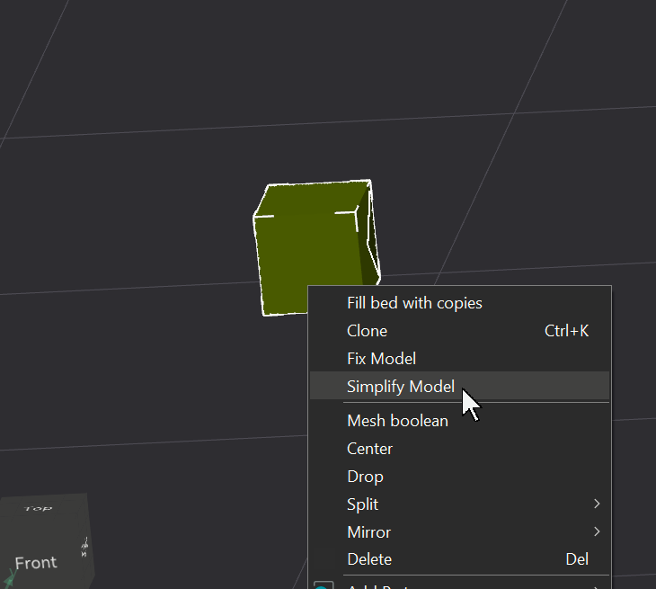
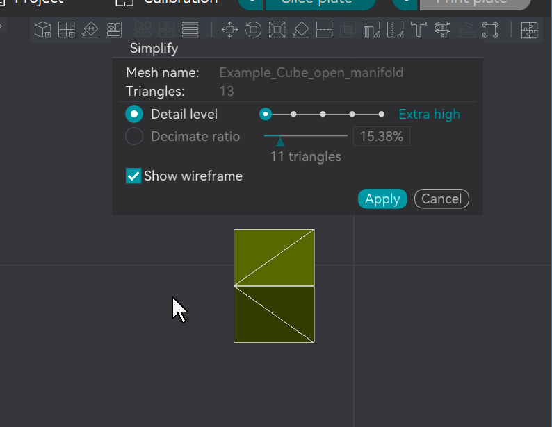
I’ve had this issue with both drawings and downloads. If I run it through the stl-fixer, the “fixed” version usually restores the mesh and it’s printable.
Thanks for taking the time to reply. I’ll upload the model when I get to the computer. I’m a little hesitant to focus on this one model though as I use the same technique reasonably regularly.
It’s Shapr3D I use, though also not so important I guess as the issue is with the slicer rather than the original drawing. Nice tip on using .STEP, I’ve always exported 3MF thinking it was best.
It’ll be more clear when I upload the model, but what I have is a print in place part, one PETG, one part PLA. The PLA part has a PETG base made for it as a print support, the PETG part has a PLA support made for it. I do this often and it’s a really nice way to get perfect overhangs.
This particular model, one piece is effectively floating because the slicer doesn’t see the support models as having collision. It’s not floating, it rests perfectly on its support.
There’s no issues with the models, each part will print fine standalone if resting on the bed. The part can’t be assembled after printing though so needs to be print in place.
I made a tiny thread that holds the floating part to the exact correct height on the bed, small enough that it won’t print, and that’s where my issue lies. Everything is perfect and ready to print but the slicer won’t allow me to send to print because it doesn’t recognize the objects will interact on the print bed.
I think my question might be answered that there’s no setting to allow me to turn off the warning, so instead maybe I need to find a way into spoofing the slicer into thinking the lower surface is just a really bad overhang.
Based on your first post, I suspected as much. It’s counterintuitive, but 3MF isn’t ideal for transferring models between programs when you’re the one controlling the model. That sounds odd - it’s a “standard,” after all - but the issue is that the standard is too open to interpretation. For example, Bambu Lab encodes colors and assemblies in 3MF differently than many other programs. So when is 3MF beneficial? It works well when saving, transferring, or uploading to MakerWorld - especially if you want Bambu-specific features preserved.
You’re on the right track, but spoofing isn’t necessary. Try selecting the bottom face of your model and extruding it downward. After exporting to STEP or STL and importing into the slicer, you’ll likely see a “zero layers” warning. Just lower the model a long the Z-axis until the original base is flush with the build plate - you’ll know it’s aligned when the build plate highlights around the model. The extruded section will sit below the plate and be clipped at slice time. The key is to close any gaps at the base; the extra geometry is discardable.