The X11 receiver and the X12 transmitter shields provide a number of inputs and outputs.
The transmitter shield (X11) offers 6 proportional/analog inputs (samples between 0 and 3.3V with 12-bit ADC) and 4 digital/binary inputs.
The receiver shield (X12) offers 4 servo outputs (PWM), 2 brushed motor outputs (dual PWM controlled H-bridge) and 2 NeoPixel serial LED outputs.
If you would want to create a remote and/or a model with more inputs or outputs, one idea would be to just use multiple CyberBrick pairs for control. This would work, but they would be independent of each other, so no cross interaction between inputs/outputs of one system with the other system would be possible (called “mixing” in more advanced RC systems). And also from RF communication perspective that would not be the best solution.
But there might be another way, not requiring too much wild tinkering.
Namely two pins on the receiver and transmitter shields can be used for serial communications (e.g. using from MicroPython library machine, the class UART).
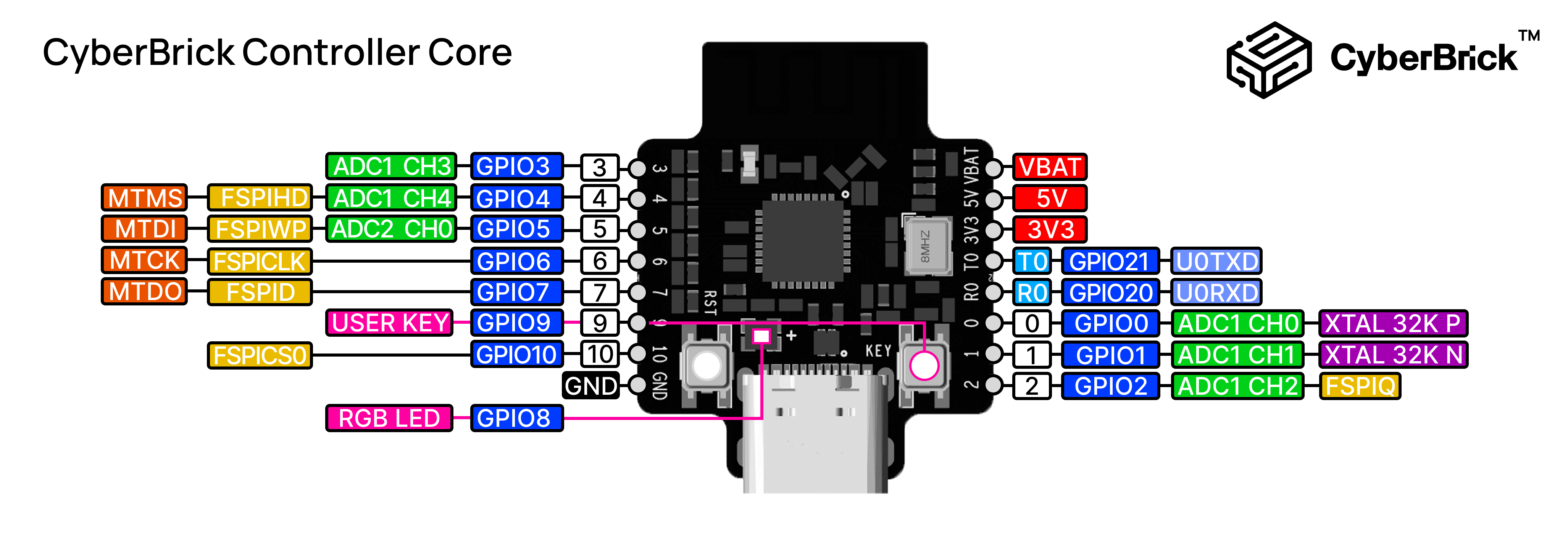
Transmitter shield (X12) pins K3 and K4 (digital inputs) and receiver shield (X11) pins D1 and D2 (NeoPixel string outputs) are connected to CyberBrick core (A11) ESP32-C3 microcontroller pins GPIO 21/U0TXD and GPIO 20/U0RXD respectively.
By wiring to transmitter shields, or two receiver shields together, by attaching 2-pin wires via K3 ↔ K4 and K3 ↔ K3 or 3-pin wires (best the power rail pin removed) on the receiver side D1 ↔ D2 and D2 ↔ D1 and then using custom MicroPython code, that is easily possible, as I have shown e.g. in here and here, we could extend the system. The communication between the shields would be via custom serial protocol, transmitted bi-directionally over the UART.
This way for example the transmitter side could have up to 12 proportional inputs in addition to 4 digital inputs and on the model/receiver side we can have up to 8 servo outputs and up to 4 brushed motor outputs.
Alternatively the NeoPixel string outputs (that by default are mapped to GPIO 20/21 and would be used for communication between the modules), could be mapped to other pins, e.g. servo outputs. This way the dual X11 module receiver could have 6 servo outputs, 4 brushed motor outputs and 2 NeoPixel string output or other combinations of them.
Alternatively could also combine a transmitter AND a receiver shield together to have, e.g. telemetry output via LEDs, buzzers or speakers also on the radio side. Or sample some values, such as battery voltage, current and so on, on the model/receiver side.
The only cable needed to be soldered/custom made, would be a XH2.54 Y-harness for the power, as I cannot see this yet being offered in BambuLab shop.