Bambu X1/P1P have force sensors in the bed, yet the tramming process is similar to printers prior to ABL.
Ideally, there will be a new option in the printer maintenance tab to perform an assisted tramming.
When this is started, it should skip all other startup routines such as cleaning the nozzle as this may cause the nozzle to hit the cleaning area on a poorly trammed bed.
When printer goes to the first location, it should display current load info, an ideal pressure range / distance, and notify the user direction to adjust the bed adjustment knob.
Once user is satisfied with the adjustment, user will press the next button which will send the printer to the next position and repeat the adjustment till all three spots have been adjusted.
At this time, printer should ask if user would like to redo or finish the tramming process. Typically at least two passes are recommended.
This is exactly what I was thinking about during the manual trimming process. I mean there’s a sensor right there, you don’t have to guess when the nozzle just barely touches the buildplate, the sensor could outright tell you when the first “spike” in pressure is detected.
I believe the current process accounts for possible offset bed location during the initial touching of the spot on the plate where it rubs the nozzle to clean it.
G0 X135 Y253 F20000 ; move to exposed steel surface edge
G28 Z P0 T300; home z with low precision,permit 300deg temperature
G29.2 S0 ; turn off ABL
G0 Z5 F20000
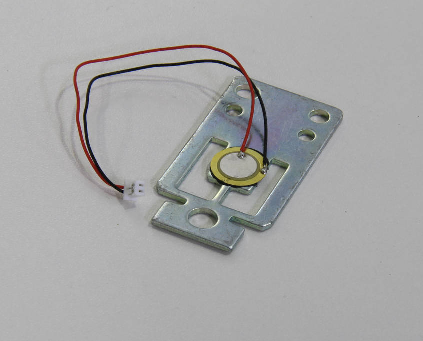
That’s physically impossible. There are no load cells. It uses three small piezoelectric transducers as sensors which react when nozzle bumps onto the build plate. They work on a rapid change only, cannot output any DC or measure actual force.
But I agree they could do tramming process better and integrate it into the firmware rather than running a very dumb G-code. They could at least run verification after tramming was done.
Not at all. Load cells are generally made of force-sensing resistors mounted on a special frame. These piezoelectric transducers are basically buzzers like used in electronic watches and other stuff to emit simple sounds. But they work both ways and can sense vibrations too. Over your wiki link, if you read description those can only work for dynamic loads. An nope, these are not piezoelectric load cells, these are glorified buzzers glued onto steel frame. Piezoelectric speaker - Wikipedia
Hi Julie, notice the G0 move before doing a home Z. I believe the Z at this point is around 10mm. My front right lead screw fell through about 30mm causing the back of the bed to lift significantly and made some unhappy sounds followed by sensor error.
So it sounds like instead of the printer telling us dynamic load info, we should change the request to have a button for probing.
Since the printer homes in the middle of the bed, we should know the ideal distance for the nozzle to travel to activate the sensors. We can then use this value vs the center distance to calculate our offset and in turn display a rotational direction and approximate amount of turn.
So each adjustment cycle would be:
Print head goes to location
Probes and displays rotation direction and amount
User then adjusts accordingly and presses the probe again button
Repeat adjustment cycle till it is in recommended range.
User then presses the next button to move on to the next position.
I did a little experiment. With the bed lowered, I activated “return to home” on the printer. As it was lifting I placed a heavy weight on the bed. It stopped briefly, as one might expect, and then started to lift again, ignoring the load. This just about proves you right.