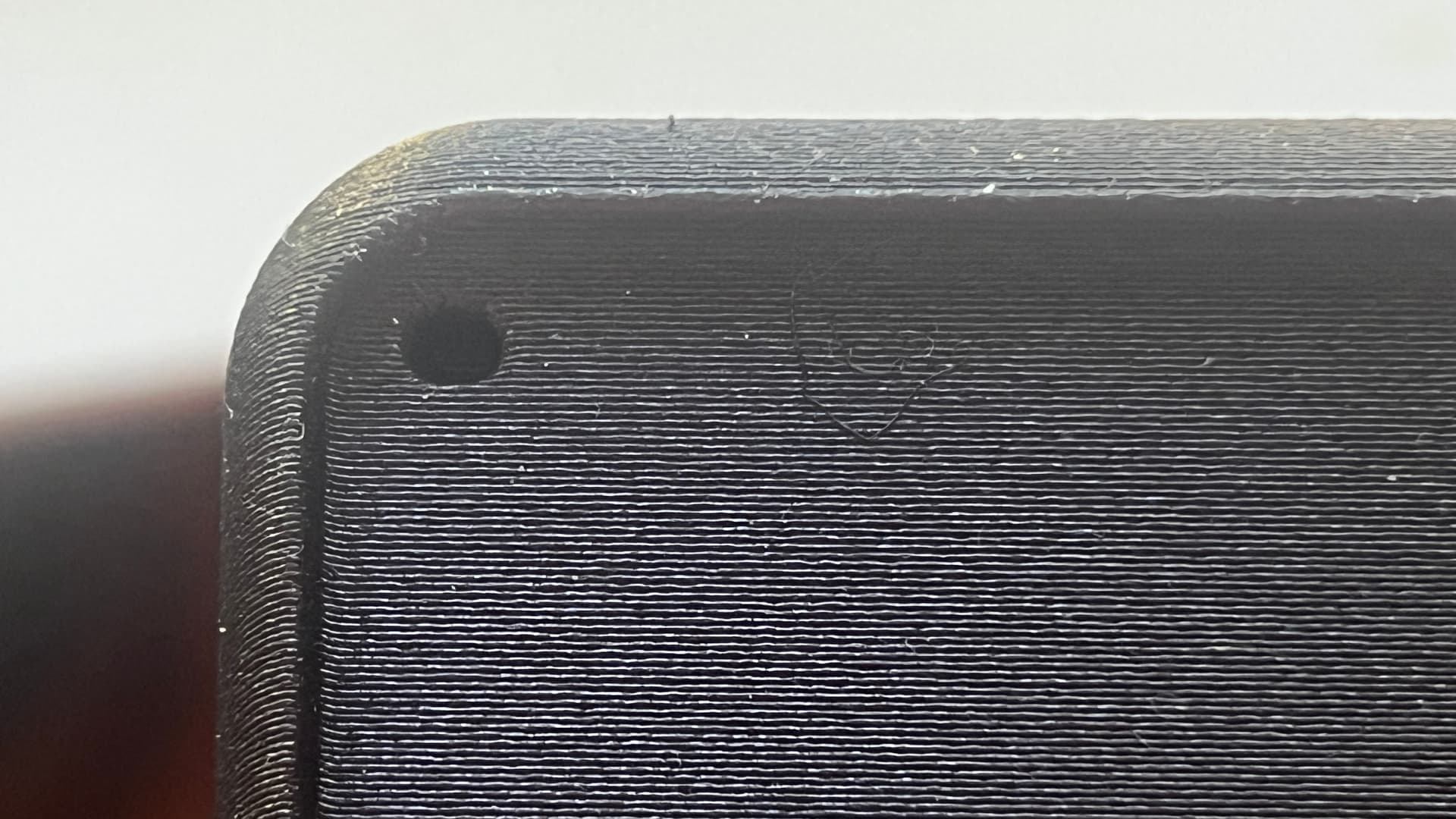
In the print: The round holes come out oval, and the hexagonal ones for bolts are slightly off. The thickness of the model is correct, so the issue is only with the holes.
The area you are concerned with is bridging (shown in blue).
It is designed to span a distance without any material underneath, as such there is nothing to stop any sagging.
You should enable supports and if automatic supports do not generate for these areas, use the PAINT SUPPORT option and change the support type to PAINT
Wow, based on the forums and various discussions, it’s clear that a lot of people are struggling with the same issue. And so far, the only real solution seems to be either using a non-Bambu Lab printer or printing vertically.
I’ve tried every recommended setting tweak—nothing worked. In the end, I had to resort to printing parts vertically, and the difference is night and day. It’s frustrating that this is the workaround instead of having an actual fix.
Like Jon said, it’s just how FDM works. When using support you can tweak how close the slicer will bring support to the model surface. The closer you bring support (the smaller the gap) the more sticking you’ll have between model and support but the model surface will be closer to the desired position.
There are water soluble supports that you can also use, or dissimilar plastics that don’t stick, where you can cut the support spacing to zero and still be able to remove it.
It’s not a problem with Bambu printers. It’s just a limitation of how FDM works. There are solutions, though. Water soluble support and dissimilar plastics can get you better accuracy in your prints but add time, cost, and effort.
if this is your design, you can add a “tear drop” cut to the top of the circle, which will mitigate, below a photo of how i did this in one of my designs:
In other words the ‘fix’ is to design with the FDM process and print orientation in mind.
Whether you are designing for printing, milling, injection molding, you have to optimize the design for the process. Modern printers have done a great job presenting 3D printing as an anything goes option but it just isn’t. It’s just another way to manufacture stuff with it’s own limitations and possibilities.
The design you made could easily be printed without supports on its side like you want but the small design choices you made make it so it needs support and will still come out slightly disappointing. Easiest rule is to give bridges a bit of extra tolerance and avoid any overhangs steeper than 45 degrees
This may not be the most practical solution but it does work: In CAD, make the holes ovular along the Z-axis. This is a bit odd to work with at first but it is a quicker fix than jumping through orientation hoops and settings. Good luck.
I used to do this oval workaround but the results felt just as bad. Instead of a crisp bottom and saggy no fitting top, you get a crisply printed deformed oval bottom and a fitting but still saggy top. You really want the “hole helpers” geometry on ONLY the section that would sag to gravity.
Another tip is to use supports when possible and make your hole helpers extend the holes by about 110% of your support top z distance, usually 0.22mm. This gets it really really close to dimensionally accurate.
I’ve got the same problem with my H2D- but it is not “normal for fdm”, it is a fault with Bambu labs- I also have a prusa I3 Mk3 S+ and a 5-head XL- they have never printed an oval hole.
The H2D prints a hole on a horizontal surface perfectly, but a small (around 3mm) hole on a vertical surface is always wider then it is tall. Most of my holes are for 3mm bolts or heatset inserts and it is a real problem with them.
When you look closely, it looks like it is trying to print the hole twice very close to each other.
Yeah, that’s is for sure an issue for Bambu Printers. For all of them - oval circles while printed in Z. My other non-Bambu printers are capable of printing circles as more of … circles.
I hear your pain, because I feel it too! All explanations lead to ‘sagging’ when sagging here is not the problem, but the shape of an oval hole which is, at its minimum, actually accurate.
This is because BL hides the flow multiplier and pressure advance under the same automation and calls them “flow dynamics”. When you turn off the “Automatic Flow Dynamics”, you can go to the Calibration tab and manually set the K value. Play around with the K value and see if that helps.
Note that, for the manual K settings to be applied, you must turn off automatic flow dynamics. Basically, it all boils down to - disable the smart flow features and calibrate it manually - make it dumb like Prusa and you might get similar results
Post back your results, I am eager to see if that helped.


 next time i need it i’ll give it a go