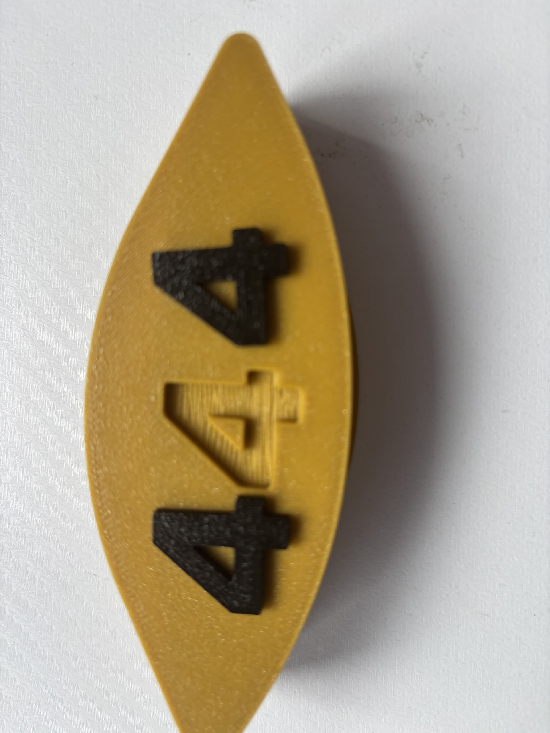
So i am printing a numbering system for chairs and it is both sided but i made the mistake of making the 2 halves fit by making them smaller so now i have 2 different sizes of numbers.
Next part of this is that any numbers that holes inside of them so 4,6,8,9,0 dont fit into the bigger half also the numbers are modeled with tolerances in mind but for some reason they only fit into the smaller half but the smaller half ones are build after the number in the smaller half. I can also incluede 3mf if that will help.
Your description is a little unclear, so this is a guess.
I believe your concern is why your scaled numbers do not fit their respective negative spaces (holes as you call them).
You state you scaled them, and based on the complaint of why and how they fail to fit, it is his you scaled them.
If we simplify the situation, image a circle. To solve your problem you would have a negative space slightly bigger than the circle that will be placed into it.
That works because the contact points between the circle and it’s negative space are moving in one direction, which is outwards.
Now imagine the number zero, this has an outer edge and an inner edge. If you scale this uniformly, the outer edge will expand as will the inner edge, yet this actually needs to contract.
You must remember the scaling needs to affect the shape and not the size.
The solution is to thin the numbers, think of this as regular vs bold font faces. They are the same typeface, but one is slightly thicker. You need to perform a similar action, but with less of a distinct change between regular and bold.
Depending on your CAD software, you should be able to trim or expand the edges of the numbers uniformly. The aim is to make the outer edges bigger and the inner ones smaller. Your software should have documentation on how to achieve this.
Than you for the answer but for example now i have a problem with the number 4 since the inner triangle and the triangle in the negative space is the problem i cant get the threshold to make the parts fit with a little resistance to hold them in but also to place the min so i dont scale down the center hole too mutch since i dont have a problem with the parts being loose but with the parts not fitting into themselves and hammering them and havig a 50/50 percent chance of succes isnt an option. It would help if u could help me find the treshold i am using the p1s. and the thing thati make the negative space and the number in bambu studio.
It should be a feature of your CAD software.
The change needs to be uniform and not achieved by manually scaling the outside and inside separately.
You then experiment as all filaments are different.
well the tihing as i mentioned to make the negatives and the numbers is Bambu Studio
You can try to make the numbers with a xy contour and xy hole adjustment applied to thin them out but what Malc said is way more correct. Simple scaling will only add clearance to the outer edges and may exacerbate clearance problems on the inner edges
thx but i really need some steps on how t odo it in the software since i am tight on time with this project.
If you’re tight on time I would suggest you should use an AI - which can reply to you in milliseconds, not a forum that responds to you in days.
Analyze this image. I am using VERY large number in the settings for illustrative effect
These are all the letter “R” in 40pt font
1: No settings.
2: SCALE reduced to 95%
3: XY HOLE set to +1.00mm
4: XY CONTOUR set to -1.00mm
5: BOTH XY Hole and contour
Which do you think would fit into a hole best, with clearance evenly distributed along all edges?
It seems like the number 2 and 3 would fit the best i am not that tight on time and using basic ai is just waste of time i just need to figure out how to set them up since number 2 works for me when i just round up the percentages down on the smaller one but it isnt the same for the bigger one.
Ok, well, you do you, good luck

