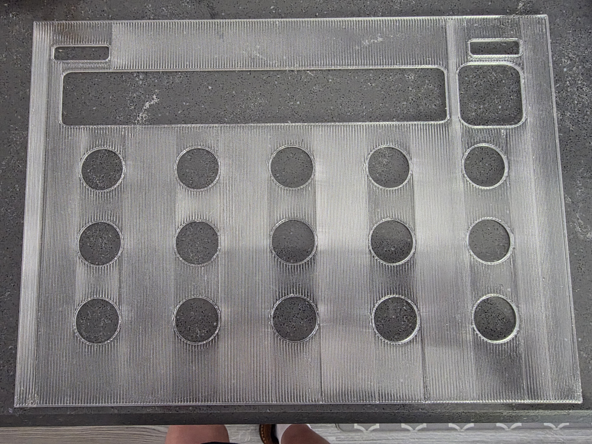
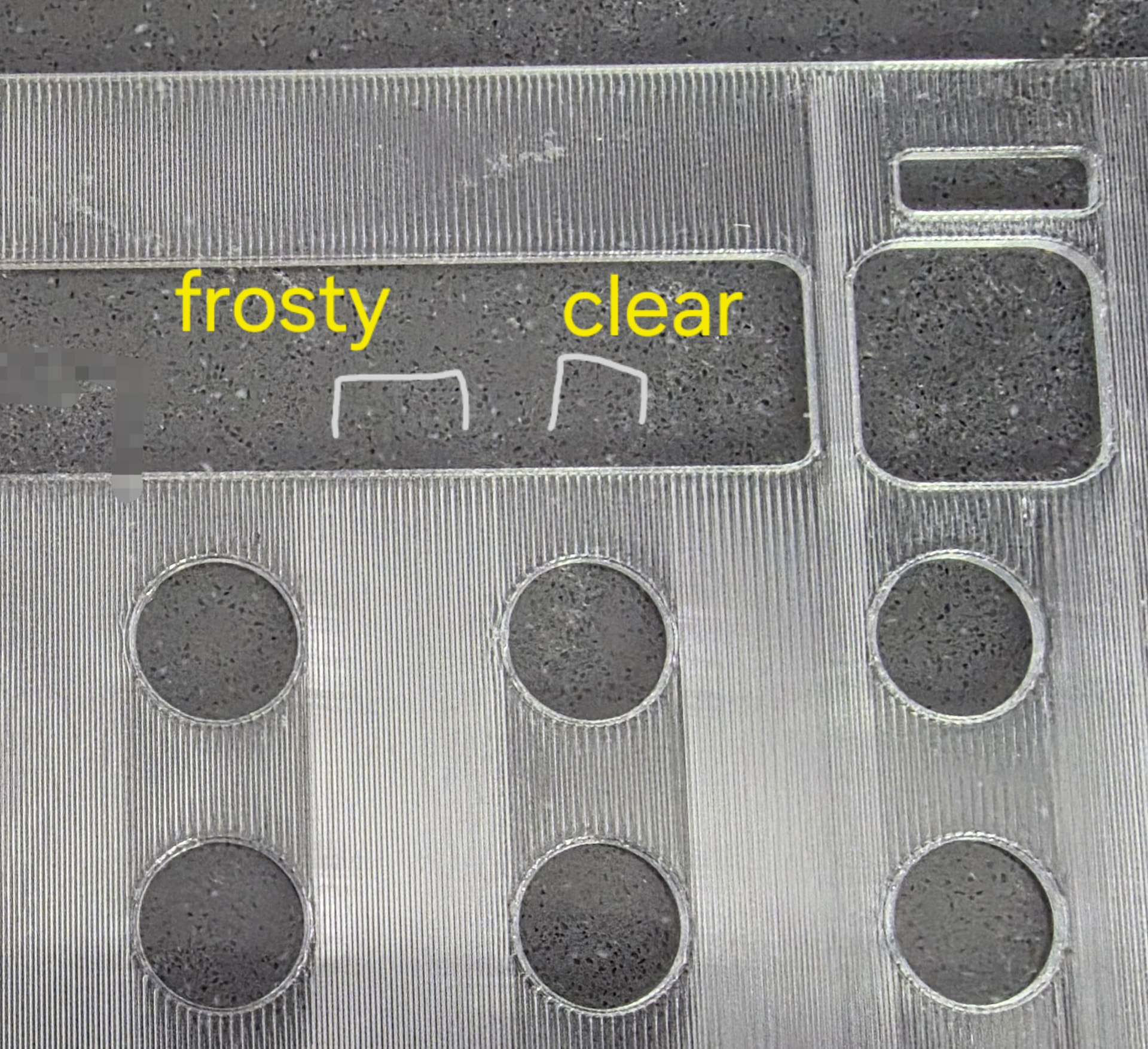
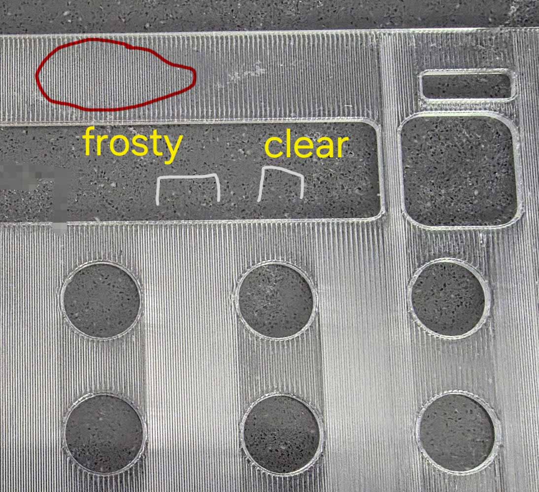
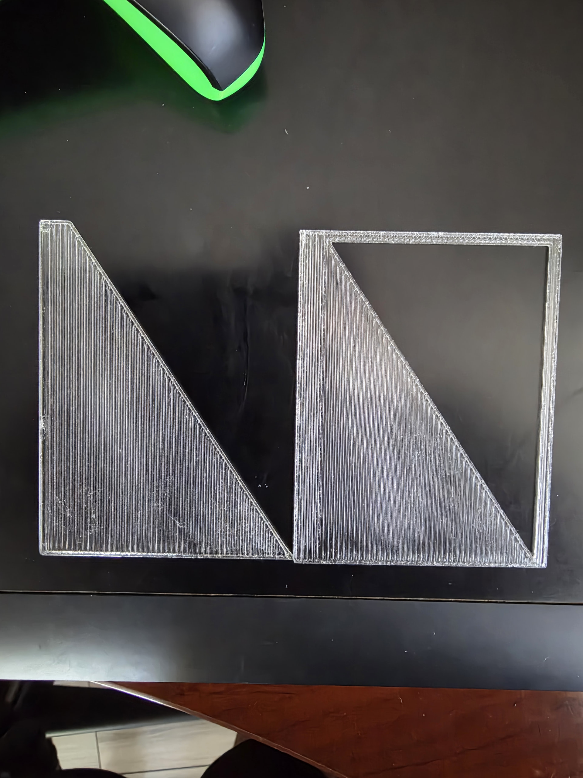
What can I do to get the infill looking equally clear (or for that matter, equally frosty) across the whole model? In this image, you can see how there are stripes where the material looks thicker between the holes, even though the model is perfectly flat and even depth.
I’m using the recommended transparent petg settings from bambu, albeit adjusted for 0.8 nozzle width. Fans are off. Speed is 20 mm/s all around. I am guessing it is still changing speed or flow so there might be a setting to force those things to stay constant; anybody know?
Check your slicer preview. Find what those line types are. My guess is “internal solid infill” but could be only a bottom and only a top. Pic doesnt show depth very well
Overall its pretty close.
Try expanding that line type’s line width slightly. This mushes more, better chance of filling all the area with plastic and no tiny ribs of air.
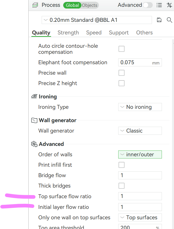
If you are using orcaslicer, you can also expand that specific line type’s flowrate slightly. If using bambustudio, you can increase overall filament flowrate but you might need to also specifically reduce top+bottom flow rates to prevent squeezeout.
It says they are sparse infill. My line widths are 0.82. I actually decreased my flow to 0.97 because it looked better in calibration. I think because the 0.8 nozzle lets out more material than expected. Do you know where to change top/bottom flow ratio in bambu studio?
It’s going to be tough to get those lines to completely disappear because the line being extruded isn’t going to melt into the preceding line perfectly each time - that’s why you see a boundary.
I’d suggest going to smaller test sections to not waste as much filament, and then try these things:
Super dry filament is a must
Higher bed temperatures
Higher nozzle temperatures
Cooling fan off
Extrusion multiplier may have some ability to help
Look into “brick layers” - a custom python script - it staggers the lines in each layer, this may help further reduce the appearance of lines.
There are also many excellent videos on youtube on the topic.
It isn’t so much that I’m trying to get the filament to be clear as I’m trying to get it consistently clear throughout. Like there are always bands that are more clear above and below holes, but the entire column between comes out frosty between them. I would prefer it to be either all frosty or all clear.
Because your object is irregularly shaped it’s going to be very hard to avoid this entirely.
You can try to use concentric for your bottom surface pattern and internal solid infill pattern.
If you want to keep that path direction, you could also crank your max print speed down to match whatever speed it’s hitting in the short sections, that should result in a more consistent look.
The other thing that comes to mind is the helio simulation; it optimizes the slicing program to achieve more consistent heating; it’s meant to achieve optimal overall part strength but in this case optical consistency is likely impacted by most of the same variables that impact part strength.
That’s one of the issues I’m having too.
Have you had a look at the preview in the Slicer to see if these differences are visible there as well? (speed, flow, acceleration, etc.)
I’m currently struggling with these ‘clouds’ in the transparency…
So is it like if I set the print speed to 20 mm/s, for the short paths, it will slow it down to a lower value? Is there a way to see what that lower value is? The slicing result viewer just shows everything as 20 mm/s, even though I can see something must be changing to cause that striping.
I ran the helio thing to see what it was. It doesn’t have transparent petg as an option so I chose petg-cf. The slicer result seemed to be showing a uniform temperature across the whole thing.
My slicer shows all parts of the model as having the same speed, flow, etc. It’s all one solid color. So either the slicer isn’t showing what the hardware is actually going, or there is another parameter that changes.
The slicing preview “speed” should actually be called “maximum speed” as it doesn’t show acceleration and deceleration, and is purely driven by line type.
Therefore, it’s not a reliable indicator for what you’re trying to achieve.
To make this simpler, just start turning speed down and heat up (keep that fan off!) until you get an acceptable result.
I think it is not a matter of speed but of different cooling time between lines due to different lengths.
Using a different infill pattern might fix this, I’ve got good experience using the octaspiral since the slicer tends to ‘grow’ them out of a certain area instead of printing long lines like presented in the picture.
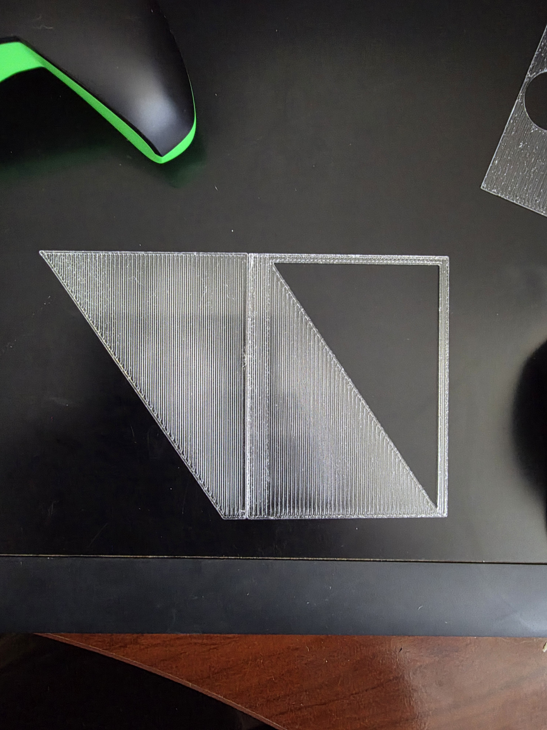
For anyone following, I’ve tried a number of different settings. The artifacts seem to depend on when you have holes. In each picture below I made two pieces, each with a solid part on the left and a triangle on the right, but the 2nd triangle has a frame around it, creating a triangular hole.
I was expecting to see a gradient where it became progressively more clear towards the narrow end of the triangle, thinking the line distance affected it, but as you can see it’s basically clearer anywhere there is an internal hole above it. Somehow it interprets the hole’s edge as different than an exterior edge.
The gcode doesn’t change flow rate or really anything as it switches from one section to the other. Visually the tool head looks like it’s going the same speed. I’ve tried varying many parameters but haven’t found anything yet. Reducing speed to 5mm/s did nothing. I tried reducing to 1 mm/s; it creates some new blobbing artifacts that make it hard to tell but think the difference is still there. Anyway what the heck?
I’m wondering if I should create a “hole” going all the way around my models to trick it, and then cut off the frame afterwards.
The 2nd Pic is just to line up the two shapes so you can how they compare.