I’m new to AMS, and while I’m pretty excited about what it can do, I’m also disappointed by the obvious gap between adjoining colors on the same layer. This is no secret – you can see it clearly in the slicer:
The result is a surface that is supposed to be very smooth actually looks like and feels like two puzzle pieces put together.
Does anyone have tips to improve this?
In some cases, changing the orientation of the print can be miraculous, because these gaps only occur in a range of boundary directions near to the z axis. But if you have non-trivial color boundaries, then you can’t necessarily orient it so that all of them avoid neighbors like the above in the x-y plane.
In theory, a smaller outer wall line width makes these gaps smaller, but it doesn’t seem that can be pushed very far before it totally corrupts the overall print quality.
It seems like going to an 0.2mm nozzle would also correspondingly cut these gaps in half, but at the cost of dramatic (at least 3x) increase in print times.
Acetone smoothing can help a little, but you can still easily see and feel these seams afterward, and that only helps with ASA and ABS anyhow.
So, I’m hoping somebody else is further along in their exploration of this issue than I am and can offer some tips!
This part was printed in roughly the orientation shown. All of the vertical boundaries between colors have super-obvious gaps that you can see and can fit a fingernail into.
I am very encouraged that at least one person has no idea what I’m talking about, because it has happened on 100% of color prints I have attempted, and the result looks exactly like the preview does at such boundaries.
So, fingers crossed that I am doing something obviously wrong!
In case it helps, here’s (part of) the same slicer image with arrows showing where this gap is. (I mistakenly assumed this was happening to everyone so the issue would be recognized immediately.)
Sure looks like a design choice to me, the colors don’t come together smoothly on the outer plane, a chamfer has been added, the slicer will not do this - it will not alter outer wall geometry this much.
This is designed for seamless color transitions and they are pretty much seamless:
The issue is not a choice but a physical limitation. As the nozzle orifice is round, any corner is rounded too. A 0,4mm nozzle can’t print a corner, only a radius of at least 0,2mm.
That is exactly what you see here.
And to be clear, this is not a bug report – both the slicer and the machine are working as intended.
But that doesn’t mean I want my part to look like that! So I’m turning to the community for ideas. I provided three in my OP. An outer wall line width of 0.25mm (the minimum allowed) does reduce the gap, but the overall surface quality suffers horribly, presumably because that is much smaller than the 0.4mm nozzle I am using. The use of an 0.2mm nozzle is just hypothetical so far, but sure seems like it would reduce this gap size by half. (The slicer estimates over triple the print time, but that might not be a show-stopper.) And acetone smoothing definitely helps – but if I push it all the way to a totally smoothed gap, it melts away some important fine features.
@lkraus This sounds intriguing. I currently know nothing about pressure advance. Any more details you can provide about how this might help and/or experiments I could try would be greatly appreciated!
I’ll respectfully disagree and point out the shot of the finished product, that transition sure seems chamfered.
Based on the limited angles of the model, i tried to find the source but could not, it appears that the green and black are on nearly the same plane / radius except for the obvious gash. There would be seams all over the place if the model had a smooth transition in that area I believe.
Round nozzle sure, and that does create complications that we address with pressure advance. But I have not experienced a channel that I can put my fingernail in on any meant to be smooth color transition I’ve ever printed.
PS: OP - the person who replied and has ‘no idea’ about this issue has designed and printed literally hundreds if not thousands of multi color models this year. I would think his intuition on this is one that is highly useful.
Oh crud! I was definitely NOT trying to be insulting there, but now I see how it could read that way. Sincere apologies and believe me I very much appreciate everyone’s help!
As usual, I entered into this not knowing what I didn’t know. Since every color print I’ve ever tried has had this issue, I just assumed that all did. I was genuinely encouraged that an experienced veteran had never seen this, because it suggested it was just my own error, and therefore easily fixable (once I found out what error I had made).
The particular part I posted is a product my company sells, but currently we paint them which is a giant pain in the ass.
So I’ve attached a contrived example for anybody who is willing to help me understand this better. Of course, this exact part could simply be printed in a different orientation so that no color seams are similar to the z axis. But that’s not always possible, and the point of this is just to illustrate the issue. ColorGapExample.3mf (24.5 KB)
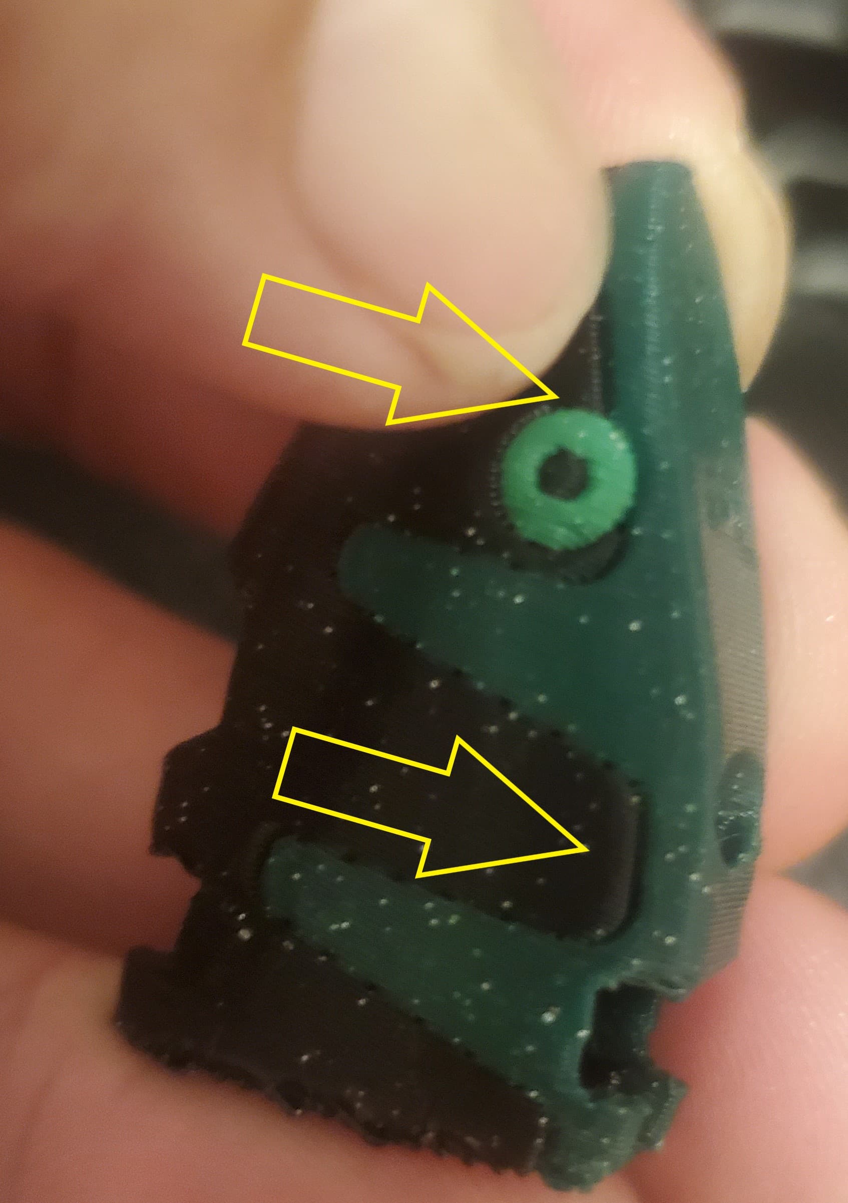
(Added a few hours later) Here’s what that looks like off my printer with default everything. The gap is on-the-order of 0.5mm at its widest, and I can easily put a fingernail into it. This is, of course, before trying some of the ideas that are posted after this one. I hope to report something good from those later!
I think the deciding difference between the part you posted and the part from the OP is, that your assembly has no borders between colors on the outer walls. The rounded corners of the green features are filled up by the surrounding grey. This is not possible at the outside.
Also notice the size of the OP’s part. It is tiny compared to yours. So the rounded edges look exaggeratedly large in the photo.
Maybe you can post a closeup shot of a colored corner with color transition in your part?
Actually pressure advance is not intended to make corners more square but to reduce overextrusion when decelerating, which causes bulging and underextrusion when accelerating, which causes the opposite.
A mistuned pressure advance indeed could lead to more rounded corners than necessary. Another feature that adds to rounded corners is the resonance suppression. Don’t remember BambuLab’s term at the moment.
The influence of both rises with printing speed. So if you printed the model at default speeds, a simple test could be printing at much lower speeds, e.g. all speeds (except first layer) reduced to 80mm/s. That is only for testing of course. If it makes a difference, you could further test, which speeds you can increase without consequences.
@Alex_vG’s comments all make sense to me. I do not have an AMS and I have no experience with multi-color printing on a layer. So, caveat emptor.
My thinking was:
A large PA value tends to under extrude near the corners, which can mean the corner line is thinner than it should be and perhaps increases that color-color gap.
A small PA value over extrudes at the corners, causing bulges at sharp corners.
So maybe your PA value is a bit too large. Bambu refers to PA as flow dynamics and has a manual calibration test in Studio. You pick the best results from a range of values, “best” typically being the one producing the sharpest corner, with no bulging, and no gaps between lines. Check that first, it will improve your entire print.
Sometimes it is hard to decide between two or three test results - picking a value that tends toward bulging (smaller number) might help fill that color-color gap. The possible problem with that approach is that the bulge tends to affect both sides of the corner. Filling the gap might also raise the outer surface.
So, that was my theory, I’ll have to leave the experiments to you.
Revisiting this subject - did you ever find resolution to this issue? I also see this exact issue and have wondered how to improve upon the transition between colors.
Actually yes – I improved this tremendously, and it was playing with @lkraus pressure advance idea that indirectly led me to it. BUT my “solution” is very hacky and somewhat material-specific.
I modified my CAD such that it is slightly thicker in a narrow region on both sides of the boundary. If you pick super-magic-situation-specific values for the width and thickness of the “augment” regions, you can actually trick the slicer into making a much more squared-off corner on both sides and really tighten up the boundary. If an ambitious programmer wants to play with this idea, I would be happy to consult. I think it’s probably possible to automate this in the slicer software.
However, since I am using ASA and then acetone smoothing it, I did not actually need to find these super-magic values for each case. I could get away with always making an augmented boundary that stuck out 0.12mm and was 0.42mm wide (on each side). Sometimes this actually prints a raised bump near the boundary, but during acetone smoothing it smooths right out and the resulting bounding is visually very tight. Unfortunately, this is not the easiest thing to do in CAD, especially because you only want to do it for boundaries that end up near vertical during the print. I guess that’s another reason having the slicer control it would be better.
Thank you @ThanBogan for the response. I am in the process of modifying my file as well similar than how you described. I was hoping for some sort of setting in the slicer that could adjust that. I guess what your suggesting would be a good idea for a script and/or potentially a slicer update.