Hi everyone,
I’m currently working on improved mounts for the Filament Track Switch and TPU Feed Assist modules for the H2C/H2D printers. My main goal is to further reduce filament feeding resistance and make the size even more compact.
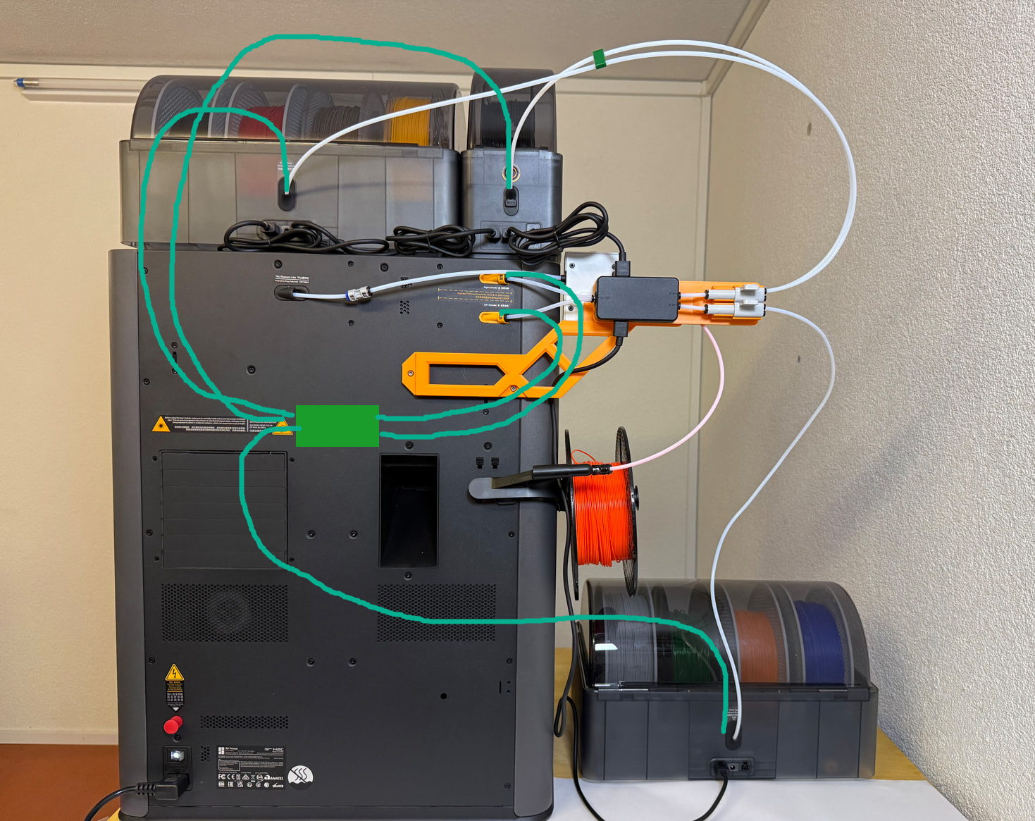
I am currently testing two different concepts and would love to get your input before publishing. The current version 2 can be seen in the first image.
The new versions 3 and 4 bring the following improvements:
Version 3 (picture 2, orange mount):
More compact and space-saving design.
Warp-resistant: Significantly reduced surface area against the heated back panel (no warping when chamber heating is active).
Improved routing: Lower TPU module position for a straighter filament path and much better compatibility with custom Riser systems.
Version 4 (pictures 3+4, white mount):
New approach, new model: The Track Switch is rotated by 90 degrees, lying flat and aligned inline with the filament inlets.
This enables the straightest possible filament path with minimal resistance.
Trade-off: It requires more space behind the printer as cables and tubes protrude at an angle.
Shared features across both models:
Thanks to the reduced contact area and redesigned mounting points, both mounts can now safely be printed in PETG without risking deformation from printer exhaust heat.
Adjustable distance between the Track Switch and the filament inlets.
Both models will include an optional variation with the TPU module rotated by 90 degrees to the side.
Which one should you choose?
If you have enough space behind the printer, I recommend to print version 4 (best possible feeding physics), otherwise version 3.
If you have already printed Version 2 and it works fine for you, there is no need to reprint!
Your feedback is appreciated:
What do you think about these two approaches? Which one fits your setup better?
Have I missed something? Do you see any further improvements I should implement before finalizing the files?
Note:
These are currently functional prototypes. I plan to release the final files after the summer break (around mid-August).
You can find my current designs on my MakerWorld profile@Steibock_3D
If the goal is to reduce filament feed resistance, yes you’ve reduced resistance between the FTS and the printer, but lining the components up like that just pushes the connection point for the AMS units further and further from the printer - if users want to stack AMSes on top of the printer the PTFEs will be getting longer than whatever was saved with this mod.
The only way this makes sense is if users want to locate their AMS units next to the printer, I’m not sure many people will go for that.
Hi, good point, thanks for your thoughts.
In my own setup, I’ve positioned my AMSs on the printer and to the left of it. This works quite well, and the PTFE tubies are roughly the same length as if the FTS were mounted in the original position specified by Bambulab.
If the AMS were to the right of the printer, then the tubing would be longer.
Your designs are looking great. My favorite is version 4. My only suggestion is to make it possible to pivot the orange part downward slightly or upward slightly to begin the turn of the filament tubing just a little sooner. Turn slightly upward for those who mount their AMS on top of the printer, and slightly downward for those who mount their AMS on the table to the left of the printer. Since the distance from the inlet to the tubing track switch is so short, I doubt that the angle could be more than about 25-30 degrees at the most, but if it were adjustable (Hirth Joint / toggle pivot) we could experiment with it. For bonus points you could actually add two pivot points into the orange part. One pivot between the printer inlet and the track switch, and a second between the track switch and the PTFE adapter splitter. I look forward to version 5? Thank you very much for your excellent work.
This looks perfect for my setup. The version 4 looks good as the adjustment should make it possible to fit in around some other shelving I have.
I can’t comment too much on the ways it might be improved without giving it a try. Probably the only thing I can see is that some kind of cable tidy built into it would be nice so the AMS cables aren’t hanging around all over the place.
Thank you so much for your suggestions. I had considered something similar myself, but never pursued it further. It would have advantages as well as disadvantages. The PTFE tubes would be significantly more curved after the track switch, and the mounting with the pivot points would become quite complex. However I’ll keep these ideas in mind for a later version. First, though, I’ll release versions 3 and 4.
Yes, the cable situation is a bit of an issue. I’m not going to develop a complete cable management system, but I’ll see if I can route them neatly towards the printer. I have an idea…
@Steibock_3D I dont have any mounts yet for my new H2C. I have the switch and TPU assist ready to go. Do you by chance want to send me the file for rev 4 I could give it a try.
Hi, I‘m currently on vacation, but after that, yes, I‘d be happy if you could test it and provide me some feedback. Pls send me per PM your email, them I‘ll send you the files in about two weeks.
I’m not so interested in making changes, more of validation that it would fit my use case. My H2C is on a stand that has a rack above it. So I need that angle that you have in your V4 to clear the leg of the rack that is close to the back left corner of my printer.
Really nice designs! V4 would be my preference, however I cant say any would work for me All of my AMS’s (3x AMS 2 Pro and 2x AMS HT) sit inside a stacker that sits under my H2C. I am in need of something that mounts at the bottom of the printer so that my filament may run upwards. Unfortunately, there isnt much that amounts to my setup and I dont have the skills to create a mount. Never mind.. hoping something will come!
I set up my H2C yesterday and am waiting on my FTS. I’m finding the color configurations a little confusing.
I think Version 4 is better for me but …. I don’t like the corresponding tube layout. I know we need to keep tube radius’s large to avoid resistance, but compared to what I had achieved with my P2S it’s a mess. Not your fault, but I really need to think this over.
I will be using a flipper with one AMS2 on top and to the left (when viewed from the front) 2 AMS-HT on a stacker. This means that I have to jiggle the layout to accommodate the TPU feed box.
hey philch… would be interested in seeing it, if thats ok? Not sure if you can message me directly or anything like that. I was going to attempt to use AI (Tripo or Meshy - dont have the skills for CAD) to see if it could help me design something


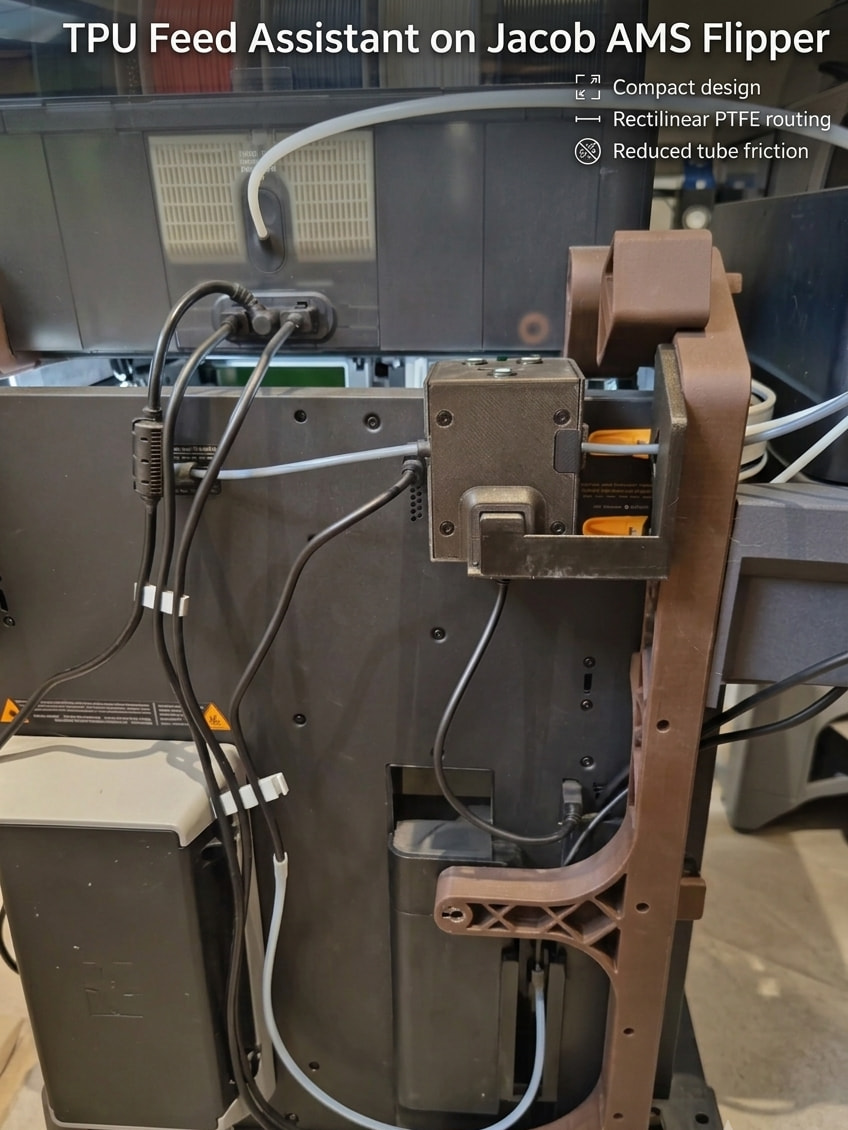

 All of my AMS’s (3x AMS 2 Pro and 2x AMS HT) sit inside a stacker that sits under my H2C. I am in need of something that mounts at the bottom of the printer so that my filament may run upwards. Unfortunately, there isnt much that amounts to my setup and I dont have the skills to create a mount. Never mind.. hoping something will come!
