I hope that I can hand my findings over to the developers of OrcaSlicer and they find it interesting enough to implement it.
I’ve been printing/testing accuracy with different filaments over the past week(s) and I have found the printer a lot more accurate that the x1c. PLA had an average deviation of about 0.03 to 0.06 mm and other types a bit more. TPU for AMS for instance had about 0.12 to 0.16 mm shrinkage.
I do run the vision plate calibration once or twice per week though. I wonder if that actually helps.
PETG HF has a deviation of around 0.06 to 0.08 here with 2x 0.4 mm HF nozzles
Unfortunately I am very far from these values, despite all the calibrations, with petg hf I have about 0.25 deviations on XY.
You should be able to go longer, Dr. Tao mentioned people using it “once a month or maybe one per quarter” in the CNC kitchen interview
Hi, I’m also a bit disapointed about the dimensional precision of H2D for holes. I own a good old prusa mk2 (10y old) that achieve better hole dimension precision…I also own the H2D vision encoder so my bambu printer should already be calibrated at the best. All my tests have been made with PLA and default parameters on both printers. It consist of a 30x30 cube with 9 holes from 6mm to 6.4mm in step of 0.05mm. Cube dimension is slightly better on bambu (0.1 precision vs 0.2) but Prusa grandMa win the holes battle : 0.05 precision vs 0.25. I know that triangulation of models affect cylindrical forms and maybe that speed is key in this area. Prusa prints takes two times longer than Bambu, so maybe that speed is at the cost of precision…
I have read heating the chamber “does it heat” will prevent it from changing shape?
True, heating the chamber slightly reduces shrinking while the plastic is stil warm. As result there is less force between the plastic trying to shrink and the build plate keeping its size. as effect, warping is vastly reduced.
But when the print is finished and while the print cools down to room temperature, it will finally shrink to the size corresponding to room temperature.
So a heated chamber helps during the print but it can’t prevent the reduced size of the final print.
That’s a big misconception people have. Just because the name Bambu is on the spool and they have a filament profile for it, doesn’t mean it’s optimized.
There is way too much variation in play for Bambu to go and optimize a filament and print profile. What they’ve done is made good average profiles, that should work okay for everyone, that serve as a good starting point towards optimization. They’re far from perfect in every scenario though.
The shrinkage on your filament, your printer, and in your setting might be completely different than mine. This is why they give us the tools (slicer settings) to optimize our own profiles.
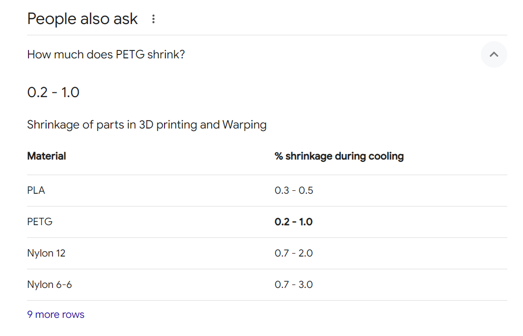
I don’t agree on this. Your statement sounds like shrinking is all over the place. It is a very well known property of most materials and does not depend on the printer. Only on the print temperature and that is also part of the profile.
In my experience, shrinkage is very consistent between different spools, different colors and even between many manufacturers.
For their own filament, BambuLab has all it needs in their hand.
And even if it is not perfect, it would bring a vast improvement in dimensional accuracy, if Bambu would make use of the shrinkage compensation in their profiles.
So I too don’t understand, while they give us the tools to optimise the motion system to within 50 microns, but they leave the elephant in the room untouched and the users have to take care of it.
The shrinkage isn’t all over the place, I didn’t mean to make it sound like that. All I’m saying is that your printers are not going to print the same as mine. Nozzle temp does have a big effect on shrinkage like you said, but you cannot assure our nozzle heaters and thermistors are reading and heating the exact same. On top of that, maybe my chamber temp is a little hotter than yours and my print doesn’t shrink as much.
The vision encoder plate was not the tool I was referring to. Shrinkage compensation was.
It’s not a setting you can just come up with an average and it’ll work for everyone. Just like flow rate and flow dynamics calibrations. Our printers might come up with completely different values even with the same filament. That is why they gave us the tools (filament calibrations) to tune our filament.
Because a lot of us grew up with the goofy inch.
I had 40 years in as a toolmaker and now model most things metric, but I still see .1mm as a bit under .004"
I can only reference actual metric size by roughly dividing ever thing by 25.4 in my head.
I know metric is superior, but my older brain was corrupted long ago.
I remember some of my early prints, (ammonia blueprint) having fractional and decimal dimensions. Now that’s even worse.
It was quite the change over the 40 years.
Of course it would not be perfect, but I strongly believe and my experience so far confirms it, that shrinking is very consistent. Much more than e.g. flow. It doesn’t depend much on the manufacturing process but solely on the chemistry. Even chamber temperature doesn’t have an effect, because it will finally shrink the same amount as my print with cold chamber when it cools down to room temperature.
And why not provide the profiles with an averaged compensation value? It certainly would improve accuracy by an order of magnitude. If you need that last step to almost perfect dimensions, you would have to calibrate yourself but for most users, an average compensation value per material type would be a huge benefit.
Because it is not the filament in this case. It is the slicer and/or printer. I’m sure it will be resolved at some point.
I know this because I can use the same exact filament with the same exact filament profile on both my H2D and my x1-c. The x1-c will print the holes exactly to size while the H2D prints them slightly under sized. If they were to incorporate an averaged hole compensation to the filament profile, now not only would the H2D be off, although slightly closer maybe, but the x1-c would also be off. Now have 2 printers that can’t print the right size hole instead of 1 and now I have to calibrate both instead of 1.
I’m fairly positive this is an H2D problem and it will be corrected sooner or later through firmware updates. Hopefully sooner.
Ahh, I see. Actually, holes being to small is not the same as material shrinking. Small holes are a result of shrinking but its not the same. Similarly to warping which also comes from shrinking. For both, shrinking compensation is no big help
Shrinkage compensation refers to the parameter “X-Y shrinkage compensation” in the material profiles, which comes into effect especially in bigger parts.
I fully agree that correction of holes is almost impossible to bake into a universal profile.
I’m surprised though, that your X1C prints holes correctly. For everything smaller than 5mm, I have to design 0,2 up to 0,5mm bigger for correct printed size.
Profiles can be machine dependent.
In other words the PETG profile for X1C can be different than the one for the H2D.
I agree, but I don’t think the holes printing too small on the H2D is a filament profile problem.
Well I’m pleased I found this thread because I have been pulling my hair out trying to fix my H2D printing holes too small. Note - I’m running the latest firmware updated 2-7-25 and the latest Bambu slicer, I ran the vision plate calibration yesterday which made little if any difference to the prints.
After reading this thread I’ve been testing with Bambu PLA and PETG and have found the following on my printer:
For holes ID ranging from 3mm to 8mm:
Bambu Basic PLA printing
3 - 2.46
4 - 3.49
5 - 4.48
6 - 5.34!
7 - 6.37!
8 - 7.43!
Bambu PETG HF printing
3 - 2.74
4 - 3.76
5 - 4.75
6 - 5.68
7 - 6.72
8 - 7.55
Outer diameters of similar sized cylinders are within 0.1mm
I have also run tests with square holes:
All ID sizes are within 0.2mm
Clearly this is not an expansion problem nor do I think it is hardware. I’m sure Bambu can improve this.
Note that using I have done reprints with compensation values based on the measurements I’ve made and the printed, corrected, holes are dimensional accurate within 0.03
FYI, there exists an earlier thread for the X1C, but a lot of the same kind of information applies to this discussion on this thread:
In particular, somewhere on that thread I posted a chart showing how hole size shrinkage is a function of the hole size. IIRC, it follows a kind of s-curve. So, in theory, you could infer a formula for that and apply an appropriate shrinkage compensation based on the intended hole size, but that kind of adaptive shrinkage compoensation is not yet in the slicer. Hopefully someday it will be! Right now it assumes all holes shrink by the same percentage, and that assumption has been proven to be wrong for a very long time now. It would be very easy to implement if they simply allowed you to enter a formula instead of just a single percentage. Any decent spreadsheet could analyze a set of measurements (preferably measured by calibration pins) and generate the formula for you. In less than a dozen measurements you could fully characterize a spool of filament’s hole-dependent shrinkage, certainly far better than is the case currently.
Thanks for this however:
Whilst your comments certainly make sense looking at holes in isolation - how does it explain the outer diameter of a cylinder being dimensionally correct and both the internal and external size of a square hole also being dimensionally correct? Does the slicer allow for expansion and contraction correctly with everything BUT internal circular holes?
Note - genuine question, I see your point and you’ve clearly looked at this I am just puzzled about why the problems just seem to revolve around holes (even if inaccuracies may be magnified by internal diameter expansion and contraction with a circle).
I’ll let other more knowledgable members give what’s probably the correct answer–or possibly confirm this guess–but meanwhile I’ll take a stab at it based on a hunch: with an outer diameter, as in your cylinder example, you can lay down an inner wall first (rememeber the inner/outer and the inner/outer/inner settings?), so there’s something for that outer wall to “press up against” and thereby mitigate diameter shrinking when laying it for greater dimensional accuracy. Otherwise, why would the slicer offer us those kinds of settings? But with a hole, there is isn’t an analogous buttress to press up against when laying its “outside” wall, which is effectively really an inside wall when you think about how it gets printed. So, as the printhead goes around in a circle, it pulls the inside diameter wall along with it, thereby shrinking the hole over what it would be if it were instantly frozen in place the millisecond it was laid. The smaller the circle, the less time for cooling, the more the pulling “off track”, and so the hole shrinking becomes more exaggerated the smaller the hole.
There! That’s my intuitive guess that makes sense to me. @user_1740592901 Do you buy it?