Mmmhmm… maybe… but dont’ you think the same could be said (ish) of a square hole?
I don’t see that, no. There you’d have each wall, being perpendicular to one another, acting as a buttress to mitigate the “pulling” when the next wall starts to get laid. And, of course, during the straightaways, there’s no pulling off track. It’s all pulled in a straight line. But in reality, I do see some of the same effect at corners, and for some of the same reasons I think.
Are you finding that square holes shrink just as much, or something?
I suppose in the limit case there’s going to be more rounding the smaller the square holes, because cooling takes time, and there just isn’t as much time on a small square hole.
It also explains why different filament types would have different amounts of hole shrinkage beyond just the material themselves: they may cool at different rates (certainly they may be emitted at different heat levels as well, which will by itself affect cooling rate), have different glass transition temperatures (denoting different cooling endpoints), and have different surface tensions, which might affect the amount of “pull” in going off-track.
If you have a different theory, what is it? I’m not wedded to mine, so if there’s a better way or model for thinking about it, I’d like to learn what it is.
No - I see almost zero inaccuracies on square holes in both PLA and PETG. This is even with a 2mm hole.
In addiition, in my current project I have a larger 12.95mm diameter hole. In testing:
PLA - Actual printed - 12.70
PETG - Actual printed - 12.85
This problem makes it quite difficult for a creator to publish files which can be printed on most devices (and especially with different material types) unless they over allow. Sometimes this is not really possible as I’m sure you will be aware.
I would agree it’s a total mess that probably can’t get resolved until the slicers improve, probably with some kind of formulaic shrinkage compensation for holes rather than a fixed factor which is supposed to cover the entire print model. We’ve already proven many times over that such a fixed factor doesn’t work well enough for holes.
Otherwise, like you say, you’re stuck using the same printer and filament that the creator created his with. Which is probably what Bambulab wants, so there’s a conflict of interest, and I don’t think it will ever get fixed in the BS slicer for that reason.
Besides, most people are too lazy to even measure regular shrinkage compensation. Using precision pins to do hole measurements to get a proper shrinkage compensation? Even fewer people. The filament makers should do it, but it seems they never do, even for the overall shrinkage compensation value.
I do have hopes, though, that makerworld will force the issue. As more people use it, there will be more failures, and more of an outcry for real solutions. Printables has the same conflict of interest. So does each and every printer manufactured backed data repository (crealityworld, or whatever it’s called, etc.). The makers need to develop a unified voice and start asking for a solution.
Meanwhile, I think the overall shrinkage is the thing to measure and worry about. With smaller holes, you can always drill them out to get an exact dimension. Not a perfect solution, but at least it’s a stopgap until there is a proper solution.
Drilling - yes but only when we are talking about holes for perfect cylinders - such as screws. In my current case it is a more complex object that needs to snap into the print which is why I ended up here 
Interesting comments though epecially with the conflict of interest situation. Never even crossed my mind.
Thingiverse squandered their advantage. For the longest time they had the biggest model repository. If during that time they had models which only printed well on their printers, then probably a lot of people would have bought their printers just so they could print thingiverse objects. Think kids or people with no talent or no motivation to create their own objects. Well, that’s why makerworld had such a big push to get big fast. They want to be the biggest and the best so Bambulab can sell more printers to those kinds of people. And since everybody is at least a little bit lazy, then ultimately to all people, and to give people print profiles that work only with Bambulab printers. Then, if you have the most models, it incentivizes people even more to buy a Bambulab printer.
Think betamax vs VHS. VHS was an inferior standard, but it won because it had the most movies that people wanted to watch, and so people bought VHS players rather than betamax players, which meant more movies were published in VHS, and so on, like a kind of thermal runaway by analogy, that gave an ever accelerating advantage to VHS. Well, the same thing is what makerworld is attempting.
A very long time ago, I heard a theory in the Ultimaker forum that seemed very convincing to me:
Imagine the moment when the inner wall of a hole is laid down, the material will still be liquid. It bonds to the layer below and the second inner wall Then it will cool down and shrink until it solidifies. The shrinking while it is still liquid causes the wall to pull inwards. It behaves like a rubber band.
Outside walls don’t do this because they are much more blocked by the other walls below and i side. It also doesn’t apply to inside straight walls, because here the shrinking only creates a force in the extrusion direction. So shrinking instead causes tension.
It sounds like a plausible model to me.
This hole accuracy thing is definitely an H2D issue. I literally print the exact models on my H2D that my friend does on his X1C, and his holes come out way closer than mine. Like significantly closer. This is consistent from big models to tiny things. I just use hole compensation, but I really shouldn’t have to.
Also, done anyone know if there is a way to specify only specific holes to apply the hole compensation on?
This is my test result, I don’t think it’s a printer thing at all.
Since my first post I’ve done a lot of testing. I’ve also contacted Bambu support who have pointed me to the “X-Y Hole compensation” in the slicer. I’ve also tested the experimental “Auto circle contour-hole compensation”. Bambu support have suggested that the problem is caused by the nozzle pushing the filament.
My testing has involved 3 different materials:
PLA Basic
PLA Metal
PETG HF.
Each material seems to produce an almost identical dimensional hole error between prints and the error is different between materials.
I’ve also tested with 0.2mm nozzles. So far only with PLA Metal.
My test print has:
Internal circle sizes 3 to 13mm
External circles sizes 4 to 22mm
Internal square/rectangle sizes 2-50mm
External square sizes 4-17mm
And other tests!
Generally most square holes are dimensionally accurate 0-5%
Unfortunately X-Y hole compensation affects ALL holes so whilst I have been able to use it successfully if there are square holes they will be enlarged.
Auto hole compensation works but only if you want oversized holes. It seems to make holes expand by a similar factor to how they shrink by default. Perhaps this will improve in time but it currently makes this useless from my point of view.
I have recorded my results on a spreadsheet and this has given me a look up table to work out what setting to use in the slicer or what dimensional additions I need to make in the CAD program (which is very much a last resort!!) Having said that the rough average values I list below works well enough.
Now I know about the problem I will be avoiding mixing circular and square holes in the same model when the hole size is critical unless there is no other option.
TLDR:
0.4mm nozzle
PLA BASIC - Generally it is out by 0.5mm, Set X-Y Hole compensation to 0.25
PLA METAL - Generally it is out by 0.6mm, Set X-Y Hole compensation to 0.3
PET G HF - Generally it is out by 0.27mm, Set X-Y Hole compensation to 0.135
0.2mm nozzle
PLA METAL - Generally it is out by 0.24mm, Set X-Y Hole compensation to 0.12
I don’t know what causes this problem. If it were filament being pushed or heat then I would expect to see square holes being at least partially affected but they aren’t and in fact they are almost perfect on my printer.
TESTING METHODS:
Mitutoyo and iGaging callipers, both callipers have been checked for accuracy with gaging blocks.
I don’t have any gaging pins but I have roughly checked small holes with known high quality drill bits.
Didn’t you find that the amount it was “out” depended upon the hole size? It seems as though everything I’ve been reading, where people did actual measurements, has said that.
arc fitting algorithm. So when printing a circle it’s generating a circle from the points of your STL. This would cause a variance.
Also input shaper.
Are we better off leaving arc fitting disabled, or enabled?
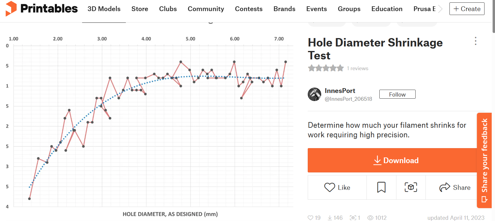
source:
Bottom line? I quote him directly:
I’ve found for some time that holes have greater shrinkage the smaller they are, even with the same filament and settings, which has driven me nuts for a long time. I finally decided to make this test and chart the results to make future projects easier.
You’ll see in my final chart for Overture PLA Rock, that at the smallest diameter the shrinkage is around -0.35mm. This increases almost logarithmically to around -0.08mm for a 5mm and larger diameter. This effect is greater for other types of filaments, like PETG, and can vary depending on brand and settings.
i.e. at least according to his measurements, the smaller the hole, the more it’s absolute shrinkage is “off”.
I can’t say whether he or anyone else is right or wrong, as I haven’t done my own measurements to convince myself one way or the other, but it does seem at odds with what some here are reporting. Everyone seems earnest enough and genuinely motivated to uncover the truth, so I assume the difference in results must be a reflection of a difference in measurement methodology or tools or technique or…? Anyone else have an ideas as to why?
still better to leave it on, arc fitting would introduce variances, but that is within the range of the limitations of the nozzle pressing itself, for extra small holes there’s really not much we can do other than drill or enable auto compensation
He’s very right, the smaller the hole, the more absolute shrinkage would be off. I would say avoid to have functional below 2mm holes on the designs. For 2mm in general you can add a 0.4mm tolerance to diameter, making it a 2.4mm hole on design but printed at roughly 2mm.
There are a couple FDM guidelines online, I’ll leave one here:
FDM Design Guide.
Besides slicer issues, material issues, the belts that we’re using are also contributing to it as belts have elasticity and a high acceleration would make it stretch a bit. This usually would be well hidden in lines given enough length to absorb the error. But for a very small hole this isn’t the case.
Here is a link to my results:
(If people can’t access this - let me know)
I only did it for myself so apologies if it is confusing/unfriendly.
The column “CAD” (C) shows the designed measurement Columns (D, E, F, G) are actual measurements taken.
I took a few measurements several times and got the same reading or VERY close to it.
There WILL be errors!
My PERSONAL results tie in perfectly with my corrections - as an example, using Fusion and printing Bambu PLA-Metal (0.4 nozzle) for a 4.5mm hole I added 0.6mm and the end result was a hole almost exactly 4.5mm diameter. I found that this works reasonably well in the slicer too (X-Y compensation of 0.3).
To answer your question - there is variance between hole sizes without a doubt
Note that PLA METAL 0.4 nozzle circle 6 - CAD - 8mm inner is further out for some reason. I re-checked this just now and the measurement is correct (based one my ONE print of this material with this nozzle). My average suggestion earlier is just an approximation based on small holes which works for my H2D.
IMHO, the easiest fix would be for the slicer to allow the user to enter a calibration table to whatever level of granularity and detail that he/ wants to. Then, when slicing the slicer can do some form of interpolation to arrive at a better hole compensation, and either ignore square holes altogether. or have else have another user supplied table for that as well. 
Totally agree… How difficult can it be to do that?
quite, you might notice that when using the measurement tool in Bambu Studio or Orca Slicer, sometimes it can detect a circle, to measure the diameter directly; but sometimes it cannot, it can only detect segments, so when you want to measure the diameter you have to manually select two segments to find its distance.
the 3d model files we use are not good at describing arcs/curves/circles, especially in a low radius.