I am modifying a multi-part model of a filament winder I built a couple of years ago to accept a DC motor drive.
I loaded the part in Fusion and was toggling between “Display Settings—>Visual Style—>Wireframe with Hidden Edges” and noticed some sort of internal structure. After flipping the entire model around multiple different ways I am pretty sure it is a logo buried inside the model.
This is not the first time I have seen someone do this and I do not really care one way or the other in general but this Logo is a lot more complex than the other one I saw (and asked about on this forum) not long after I started using my BL printer.
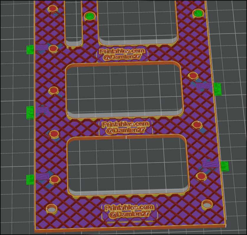
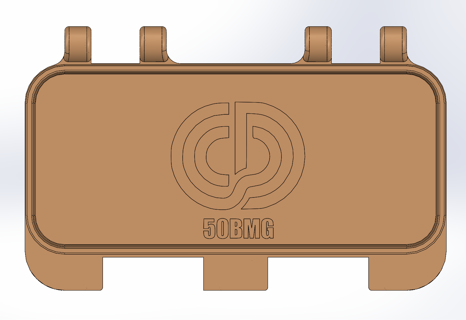
I exported the model into Studio and this is what is buried inside the model. There are 3 of these things.
Does this impact print time in a material way? This 3D Signature/Logo is 20 layers tall. I can remove it easily enough but if it only adds a couple of minutes to the print I won’t worry about.
The internal logo parts certainly will add to time and complexity, with extra movements, presumably slower wall speeds than infill speed, and so forth. It’s a cute idea (and I guess I understand some of the designer’s motivation/intention here) but seems entirely superfluous from a practical printing standpoint. Unless those solid text areas are also meant to add strength (w/out straight lines which may increase warping)?
This is just my personal opinion - I’m not saying I’m right.
I’d be more concerned about you using grid as infill in a functional part that should provide stability than I would be about a logo - and if I’m not mistaken, your wall thickness is only two as well.
Honestly? In this context, you don’t need to worry about the Logo at all. I’d rather you took a moment to think about your slicing settings for the functional parts.
Edit: Here’s a link on the topic of infill, in case you’d like to read about it. If speed is what you’re looking for, there are better infill. If stability is what you’re looking for, there are better options.
The logo is only embossed by 3 thou. You can see it fine when looking at the model data, but its so shallow that it gets blended in because of layer heights.
So much slander on grid infill. Its not the best choice but it is not that bad.
The innertext definitely alters the strength profile. I dunno if significant enough to be measurable, and it might even be positive lol. If you have any doubts about structural, add a wall, and curse the guys name
That’s often the difference in my way of thinking, and why my suggestions are often valuable, sure, not always:
I always look at the big picture. When you say you want to save time and filament, I don’t just see a logo - I consider your entire concept - the model as a whole. Everything is tied together and affects structure, strength, filament consumption, and speed.
If it’s just about the logo, not speed, strength, infill, etc. then there’s no need to start a thread, since you’ve already given yourself the right answer:
…and I don’t mean that in a negative way, but what else is there to say about? I mean, you can see with your own eyes that it might use about ~5g more filament from a 1.000g spool.
However, there isn’t much more to the topic if we’re only supposed to talk about the logo, not the model as a whole, I guess?
Adaptive Cubic is also of the best infill options for large objects, such as figurines or decorative pieces - only love for that kind of infill. I agree with you.
Personally, I wouldn’t use it for functional parts - that was the context I was referring to. As described by OP, a filament winder.
I have an already built assembly of this model which I have unspooled many non-Bambu filaments onto Bambu spools. I save my Bambu RFID’s which I tape to said BL spool. Color is irrelevant. I can edit the color in Studio.
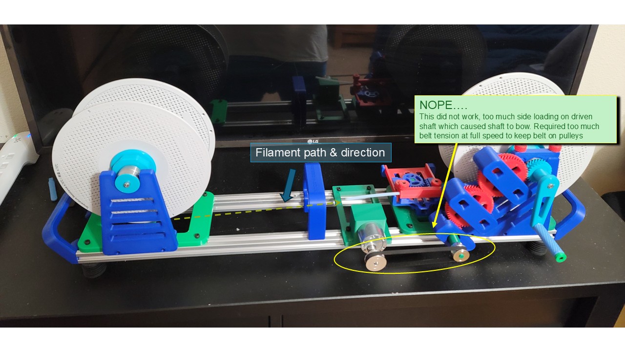
I also have a DC gearmotor that I made a very clunky OpenSCAD model to hold motor onto the frame. It was coupled to the drive side of the winder by a toothed belt drive. I powered it all with an antique Radio Shack variable DC power supply. That style drive system was not good. There was too much side loading of the driveshaft which caused it to bow.
As is my nature, I want to see what something like that machine is capable of. To that end I put some random Amazon bought filament on the donor side and wound that onto to Bambu spool with the Radio Shack power supply turned up as high as it would go. Those spools were a blur they were moving so fast.
It was scary but not because of a weak base plate. For that particular application and what that base plate was doing, it has ample strength. Were it under some sort of unsupported strain, yes then it would be an issue. The load is on the long axis of that plate, not the short axis. The maximum load that base plate is subjected to on the long axis is the tensile strength of the freewheeling filament.
Like many functional 3D models out on the internet, they are really, when you get down to it, prototype designs that most of us do not have the capability to run through a rigorous testing campaign.
That base frame, when assembled into the complete machine has ample rigidity. The base plate was mounted via through bolts to 2020 aluminum extrusion beams.
Had you seen the couple of full speed runs I subjected it to, you would know that the machine was going to fail from a lack of rotational balance long before it was going to fail from poor baseplate rigidity. I had to remove the hand crank very early because I could not even approach full speed before shaking started. My current thinking is direct coupling of motor to drive shaft. I made a crude coupling just to visualize and I do not like how far out the entire motor and coupling stick out.
I regularly add internal structure to my models. I have discovered that an engineered internal structure can make for a stronger print than printing it solid. Which is to say that internal structures tend to make 3D prints stronger. Unless the logo uses a different filament it should add very little material or time to print - insignificantly so.
 is enough. I really appreciate it.