Keeping Hole Size the same when using the Scale Feature -Bambu Studio?

Hi Everyone,

  1. I have been trying to simply lengthen one side of an existing small L-Bracket file that has predefined holes at each leg. When I lengthen one side, it changes the existing hole size into a stretched oval hole. Can you advise how I should be doing this to keep existing hole size?

  2. Also, is there a way in the above example to change the hole size (say if I wanted to have a larger or smaller hole than the predefined one in the file)?

Thank you very very much everyone, my first post and have been learning a bunch from the experts here.

Gary
Alpine Racing
Bambu Labs X1 Carbon

The TL;DR answer is: NO.

You could try to use the X-Y hole compensation to increase the hole size. That would only get you halfway.

In this example, the hole in one object was increased by 1mm

______________________________

I can only guess what your attempting since you didn’t post an screen grab but it sounds like you’re trying to use the scale feature by scaling one axis. The correct tool is to use a Parametric CAD tool to modify the hole by mathematically changing only the hole diameter. Slicers are not that tool. When you scale you scale the hole model. The slicer doesn’t know the difference between the hole or the surrounding material.

There are many free CAD programs out there so money is not the issue. However, if you have a model that you wish to modify using the Slicer and all you want to do is change the dimension in one area, you could cut the model, then stretch a piece of it then reattach the center piece and then merge the pieces into one model again.

Here’s an example. Please note that this is a very time consuming process that would otherwise be done in seconds in CAD. There are probably other ways to do this but this is the way I used to do it, wasting hours, before I started using CAD.

Step 1 - Cut the object twice along a solid boundary that can be lengthened without changing the geometry of the entire bracket.

Second cut

Step 2 - Orient the pieces using the move command

Now that you have the object into 3 pieces we can arrange them on the build plate and use the center section to lengthen it.

Note: I’ve added a false color for visual distinction, this is only to make the example easier to see.

Lengthen the middle using the scale command

Separate the pieces so that there is a gap. It is easier if you simply extend them along either the X or Y axis to maintain alignment

Step 3

Assemble the left hand side with the middle and fasten the faces using the face assembly tool.
image

The assembly tool will mate two faces to each other. If you have only moved the pieces in one axis, it’s easier to join them.

Repeat this for the other side.

Step 4 - Boolean merge these objects to make one model.

You’re not done yet.

Before and After

3 Likes

Huge thank you for the very detailed reply and instructions @Olias , very much appreciated… wow, that is a ton of work as you say using the slicer. Any time I spend on this should be getting more proficient at CAD based software.

PS: This was the file I was trying to change and of course the oval hole result:


Right+Angle+Bracket added height.3mf (383.3 KB)

Thanks again,

Gary
Alpine Racing

MeshMixer is maybe a little easier to master if you have no CAD skills, and it can be used to modify geometry the way you want. Download a copy of “MeshMixer”, load your STL, select the polygons that includes the hole and the end of the bracket, and then move them however far you need them to be moved.

MeshMixer is owned by Autodesk, the AutoCAD company. There are lots of YT tutorials. You need to watch the one on selecting parts of an object and the one on the use of the transform tool. Maybe 5 minutes of viewing. 30 seconds to make the changes you want once you’ve figured out how to do it.

Also, those brackets will need supports to print the way you’ve oriented them. I would take the “gusset” (the triangle in the inside corner of the bracket) and use Meshmixer to move the up/down facing faces to be aligned with their respective bracket edges. The triangle will be as wide as the bracket. So it won’t need supports. Bonus, the bracket will be stronger.

1 Like

You don’t need full CAD software to hack this together, you can use organic design tools like tinkercad/3d builder/meshmixer. (mild warning on tinkercad’s export - low res, bad for organic curves, but not noticable for simple stuff like this bracket example)

  • 0.1) Measure the holes size, or determine the size you want to have in the end product
    1. Add some cubes, scale them so that they fill in the holes, group/combine these objects together.
    1. Scale this solidified object to your desired size.
    1. Recreate screw holes as cylinders / cylinders-with-a-cone-on-top, sized as you want. Make these a negative object.
    1. Place them as you want, group/combine the object to cut the holes.

To show you how it can be done, here is the file. Admittedly, this has some rough edges but this is what I can do in 10 minutes. In CAD it would be seconds.

Right+Angle+Bracket added height modified.3mf (455.5 KB)

Since your dimensions were conveniently 40mm and you wanted to grow it to 80 mm. These are the steps to do it. Just cut out a middle section and lengthen it to desired dimension then glue the pieces back together. The bug drawback in this approach which CAD would remedy is that your angle brace didn’t scale in this example. I supposed one could just stretch it and it would scale accordingly like this:
Right+Angle+Bracket added height modified long angle.3mf (483.0 KB)

steps to recreate. “This is a rushed example”


In this last image, you can see that the holes are intact.

2 Likes

First, thanks for taking time to make the detailed guide! I’m sure that’ll benefit people.

So my question is whether you know of any CAD suites that actually actually make a hole resize as quick as you suggest, when given the STL files that dominate MakerWorld? I’m not aware of any that can convert meshes without making a zillion-triangle mess. Even when provided a generic STEP file, it’s still somewhat of a process IME, since you don’t have the original sketches to update. I would love if you’ve found a program that can do either of these with any efficiency, though. (That said, AI-enabled mesh-to-solid converters are surely right around the corner!)

Of course when I design things myself I try to properly parametrize things, which does make a change like this a matter of seconds. For the same reasons described here, I try to only print designs that include the original source at well. (Drives me nuts how many designers choose an open source license without including the actual source!)

Anyway, to get back to my main question: Do you know of any CAD software that can actually succeed in those scenarios? (I’m guessing you meant it would take seconds to change assuming you’re already working with a parameterized design…but on the off chance you actually mean otherwise, I definitely don’t want to miss out, haha.)

I understand this is not a method to adjust your current bracket but I have been using the Bracket Generator for all my brackets, It is an awesome tool:

Welcome to the community.

The short answer is: No, there is no CAD software that makes this easy - and believe me, I’ve been searching for decades. My interest dates back to 1997 when I first used Pro/ENGINEER (now Creo). Back then, I was focused on converting CAD files for raytraced rendering in marketing materials, not engineering. Even after all these years, there’s still no “great” solution - I get by using a mix of online converters and desktop tools. If anyone knows of a better method, I’m all ears.

You already understand the difference between STEP and STL meshes, so here’s the core issue: only one CAD program comes close to recovering arcs and circles from a mesh without a multi-thousand-dollar license, and even then, it’s far from perfect. Fusion 360’s paid version includes a “Prismatic” feature that attempts this, but at $680/year, is it worth it for a single feature? Autodesk’s Meshmixer can accomplish similar mesh cleanup and face grouping for free, though it doesn’t create parametric geometry.

For a demo of what Autodesk claims Prismatic can do, check out their July 2021 update at the 3:50 mark. If it truly works that well, it’s impressive - but I’m not spending $680/year for something I only occasionally need and can partially do elsewhere. If cost isn’t a concern, try it and let us know if it delivers:

Prismatic essentially converts a mesh into editable face groups, but that’s just step one - you still need to redraw geometry to make it parametric and scalable. Shortcuts exist, but they just shift where you spend the effort.

Bottom line: there is no “best” solution.

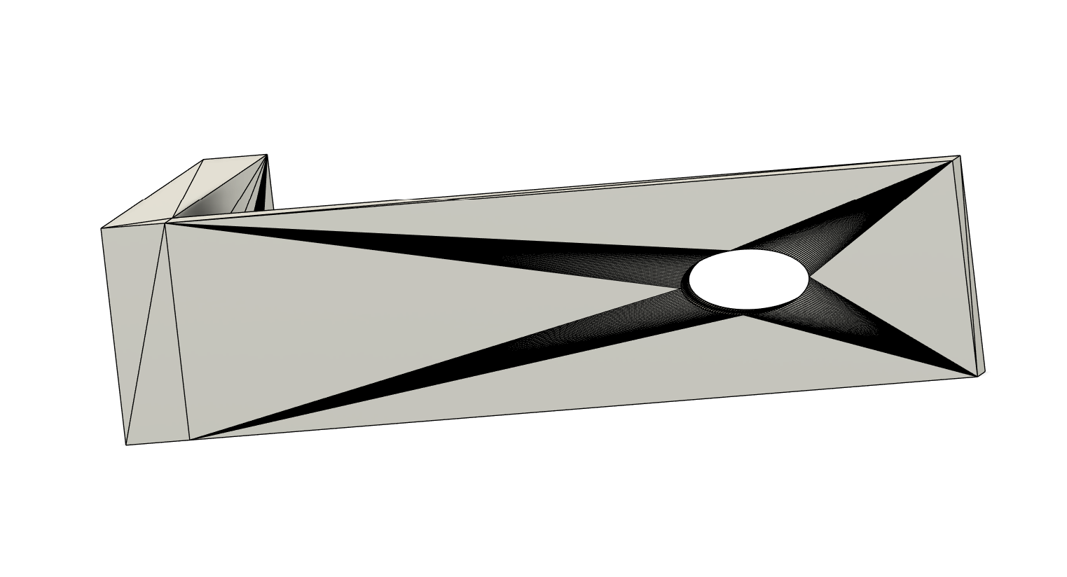
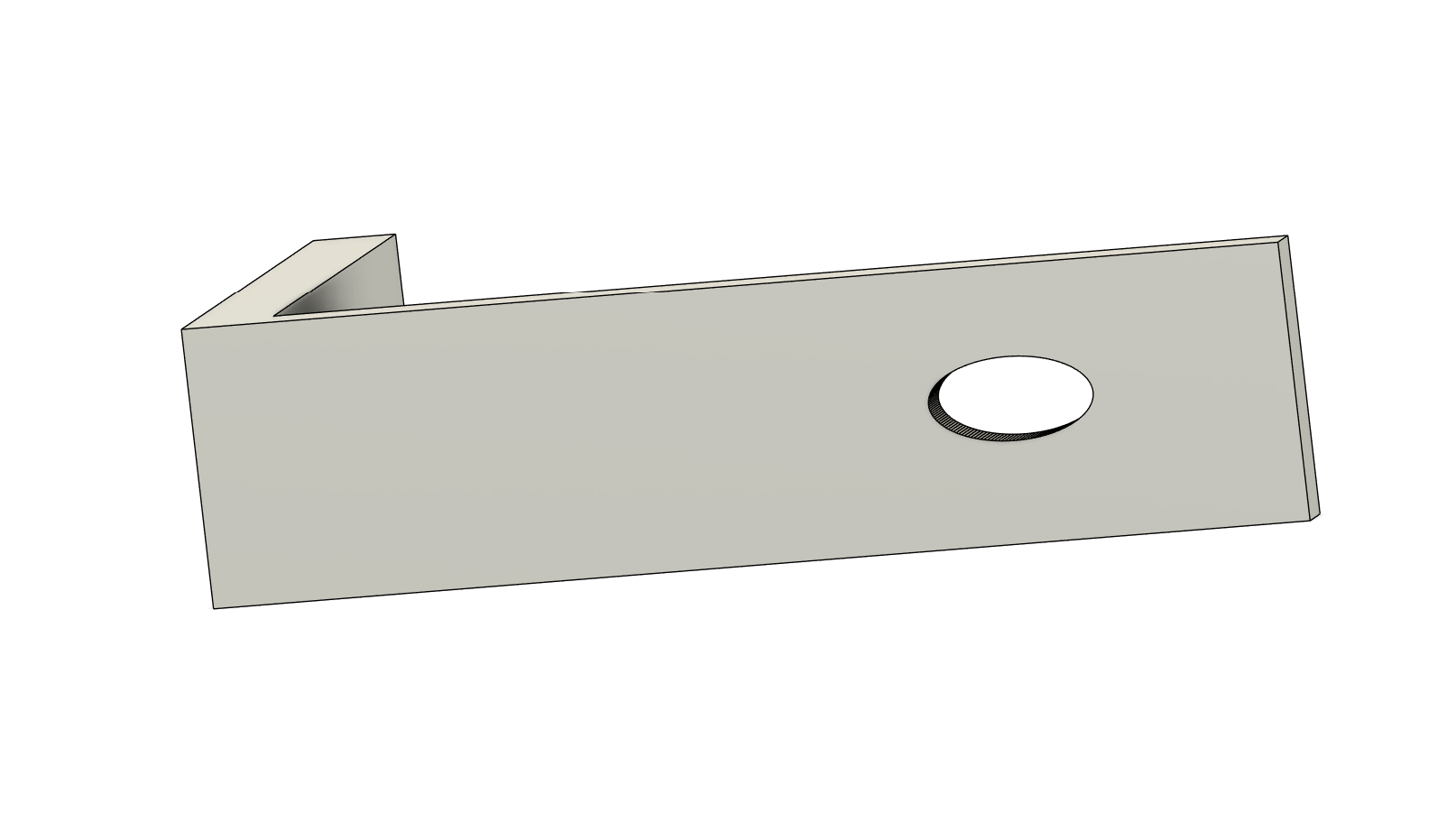
I use both Fusion 360 and Onshape, starting with Onshape and switching to Fusion 360 only when necessary. FreeCAD 1.0 also finally released in 2024 after 20+ years of development. Its STL-to-STEP conversion outperforms the others but comes with a steep learning curve that’s worth it if you’re serious about this workflow.

If you want a practical guide on handling STL meshes in CAD, I highly recommend this Teaching Tech video using Onshape:

If you only want to make a hole parametric, a “zillion-triangle mess” shouldn’t be a hindrance, make a new sketch on a parralel plane (best planar with a triangle) and fill the hole (by drawing a shape bigger than the hole and extruding it). Then simply reuse the sketch to create a new parametric hole that you cut out with a new extrusion.

In fusion you also can click on a triangle to remove it and it will usually completely clean the whole surface around as well. It can even clean the whole model if you are lucky.


Splitting the model with a plane cut can also sometimes have the same effect.
And all of this is done in the free version (outside of the free trial).
Otherwise the paid version can generate a pretty clean model from the stl to begin with but the fusion licence is a bit expensive (you can always use a new free-trial when you really need it).

Here is the file with the whole process, from the oval hole to the parametric one (passing through the cleanup) that took me about a minute.
I can’t put it here directly, apparently, but I found this site to share it with a link. It will expire in 3 days however, otherwise I can send it to you through MakerWorld probably as well, should you be interested.
“LinkFileShare - Share Via Link | Upload & Share | Transfer Files Anywhere”