Laser alignment issues on pre-cut blanks (Bambu H2D 40W)

Hi everyone,

I’ve been running into a frustrating alignment issue with my Bambu H2D equipped with the 40W laser module, and I’m wondering if anyone else has experienced the same thing.

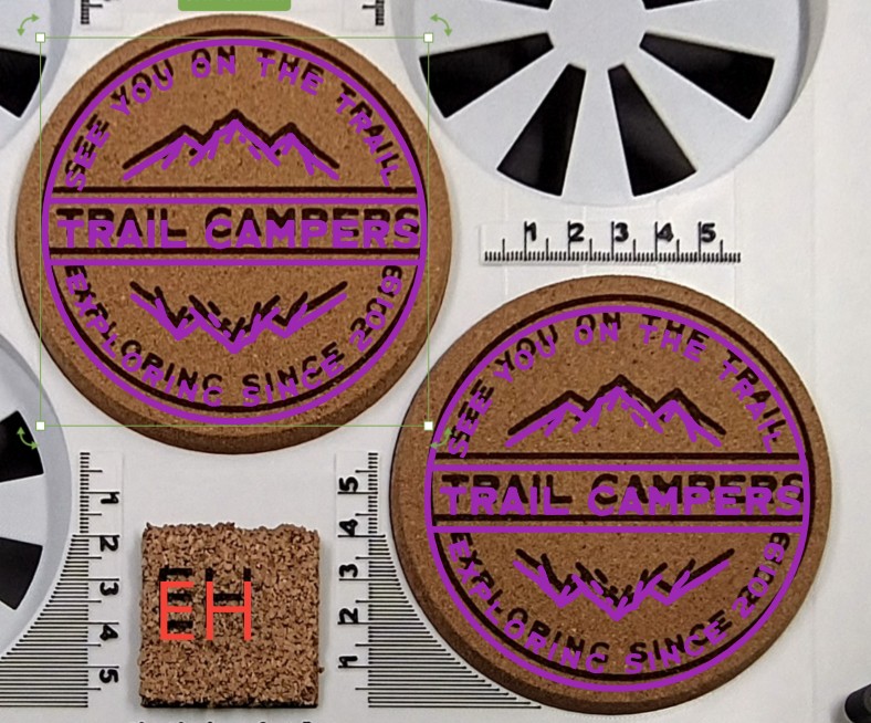
When I’m doing laser fill or cut jobs using a single sheet of material, everything lines up just fine as expected. But when I try to engrave or laser-fill text or images onto pre-cut blanks (like cork coasters or tags), the final engraving ends up being offset from where it appears in Bambu Suite—usually by about 3–4 mm, often above or to the side.

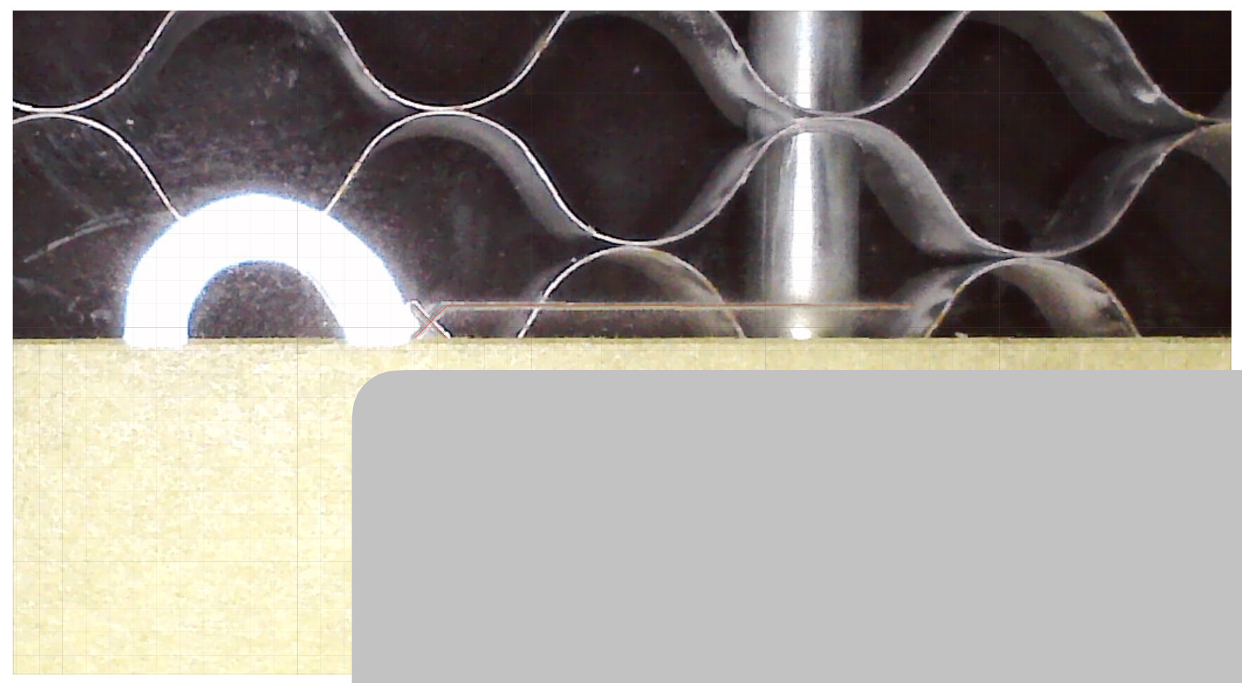
This is a real issue when precision matters, especially for products where centered designs are critical for quality (e.g. coasters or tags). My current workaround is to make and use a jig with measured recesses to hold the blanks at a consistent height (9 mm in my case, with the blanks themselves being 10 mm thick), then do a few test runs and nudge the image manually in Bambu Suite to compensate. But that’s obviously not ideal, especially for repeatability.

I’ve attached screenshots to show the position in Bambu Suite (pink overlay) vs the actual laser result on the cork (black image) for reference. this was after some trial and error to find the correct placement to get the imaged engraved where i wanted it.

So my questions are:

  • Has anyone else seen this kind of misalignment when working with pre-cut items?

  • Is there any way to recalibrate the bird’s eye camera?

  • Is there a way to get a live camera view from the laser module itself to check positioning?

  • Or maybe a feature I’ve missed that allows for image position offset calibration?

Any advice, tips, or confirmation that I’m not going mad would be massively appreciated! ive also raised a ticket with Bambu just for good measure.

Thanks,
Jay

1 Like

This is pretty typical for lasers, for a bird’s eye camera’s nature, but the extend they are off was surprising to me.
While I can’t say much on H2D’s case as mine is only the combo, I own a xTool P2S + M1 (the most mainstream desktop lasers atm) so my insights should still be useful.

The M1, a cheap 10W diode laser, has a single basic and grainy bird’s eye.
The P2S, a 55w Co2 laser, comes with both a bird’s eye and a toolhead camera, the later is used for high precision imagery positioning.

This is kind of inevitable when a birds eye’s slanted image gets remapped on to the processing plane, some areas will be more accurate the others. You can try improving the algorithm, but I suspect it just won’t go too far, which is why P2S put in a second HD toolhead cameras instead of trying to use algorithms to ‘solve it for free’.

If bambu doesn’t provide a way, it’s out of luck. They should really just like the P2S let you use the toolhead camera to produce a more accurate close-up shots.
Your jig seems like a pretty good approach. Do check whether you’ve entered the total processing material thickness.

On accuracy:
M1’s bird’s eye, ~3mm off.
P2S’s bird’s eye itself, ~1-2mm off.
P2S’s toolhead camera, when accurately ‘centered’, I can get it to ~0.1mm accuracy, which is half of its laser spot size.
(Why ‘centered’: a close-up shot is still a stretched and remapped image, so you’ll want to place the lens directly above the ‘reference’ point, where it will be the most accurate)

One of my recent projects involved 800 pieces of double side scored, engraved, cut clear acrylic that all had overlapping geometries on both sides so this accuracy was paramount. It’s not quite CNC probe+fixture level accuracy, but magnets did a pretty respectable and efficient job.

For me this works much better with the H2D. I’ve cut a bunch of 30cm wide pieces out of 30cm Sheets, which means I need to align them perfectly with the material in order to not be off on one side and it worked just fine multiple times. Also I’ve engraved some smaller metal pieces and never noticed it being misaligned at all.

I’m pretty sure you can recalibrate the bird eye camera. IIRC I’ve seen that in the calibration Menü on the printer.

You can fix this with a “jig”.

Lay out your artwork however you intend it to be positioned. Enclose the artwork with an outline of whatever the blank is that you intend to engrave. Install a sheet of paper or some corrugated cardboard on the bed, tape it down at the edges. Then, laser cut the outline of your blank. Then open the door, remove the material you’ve just cut free, put your blank in the resulting hole in the paper/cardboard you taped to the bed. Then go back and laze the engraving patterns. Everything should be perfectly aligned. You won’t have to make use of or depend on the camera.

My Glowforge has a camera and is supposed to be capable of achieving good accuracy. It never has, in spite of many attempts to calibrate it. This “jigging” method is how I ensure alignment when, for example, I’m putting a Macbook in the machine to engrave the cover… I don’t really ever use the built-in camera.

4 Likes

Hopefully, when they implement 3d meshing for the laser, we will be able to use that data instead of the birds eye camera. Using the laser lidar to scan all objects on the bed.(I believe thats how it will work) Youll also find that lining up a square pattern to a square piece if material isnt so great either. Because of the train track affect you get from the camera being offset to the front top corner instead of top center

Im having alot of issues with this, the camera just seems about 5mm off. If i line a cut up 2 or 3mm from the top edge of the material in studio it will miss the edge line, now having to place everything a bit lower but its tough when you are cutting 295mm pieces out of a 300m square

I’m hopeful that Bambu can develop some sort of image X-Y offset adjustment using the material calibration utility they already have for the live view camera and material setups. It should be relatively straightforward to implement within the Bambu Suite software, without needing to reprogram the printer firmware itself.

For now, I suppose we’ll just need to work around the issue

The above suggestion jig option would probably be your best solution. Although I have to say that so far my experience with the Birdseye cam and the 40w laser has been spot on. When I lay scraps of material in, I place my parts to cut 1 mm from the edge and the outcome always lines up exactly with the digital preview. I do use the Vision Encoder plate though every so often to make sure the motion system is correct. That might be something to try, if you don’t mind throwing money at the problem. :confused:

Have you tried placing a square pattern on a square piece of material? The pattern stays perfectly square but the material doesnt. Because of the train track affect that the offset camera gives.

From the cameras perspective, the top of the square material is narrower than the bottom.

Hi,
I’m having exactly the same issue as the original poster. I also frequently laser engrave 90 mm cork coasters, and getting the design perfectly centered is incredibly difficult.

Like you, I’ve 3D-printed a custom jig to hold the blanks in place, and over time I’ve figured out roughly how much to offset the design—depending on where the coaster is positioned on the build plate. For example, items placed further towards the back usually require me to shift the image slightly forward in Bambu Studio to compensate.

But honestly, this shouldn’t be necessary. After running the camera calibration process, I’d expect the preview to be automatically distorted or corrected in such a way that the positioning is actually accurate—especially for pre-cut items. There must be a way to improve this.

Bambu support have been pretty good in my conversation with them and it is something im told that there R&D department is looking into, so im hopefully this will be ironed out in time. :crossed_fingers:

2 Likes

I really wish they can use the motion calibration plate to get better distortion correction done. Or they could just publish a model with more markers on the plate to let us print out and do the calibration. Sadly not yet.

so im hopefully this will be ironed out in time

any news on that topic?

nothing as far as i know, im going to be doing some lazer cutting tomorrow so maybe i will see if there is a difference since the last update

I found a solution that works, at least with my coasters. I add 1 mm to the thickness, arrange everything, and then subtract the 1 mm to return to the real thickness before I start lasering. That works for me. :wink:

But that does not help with my other laser problem :wink: