Hello, I’m hoping for some help. I’m prototyping a part with a split pin. When I print it, there is a visible “groove” around it, corresponding in height to the top of an nearby feature. This is a weak point and the pin is easily fractured at that plane, by squeezing the pin.
But here’s the weird thing:
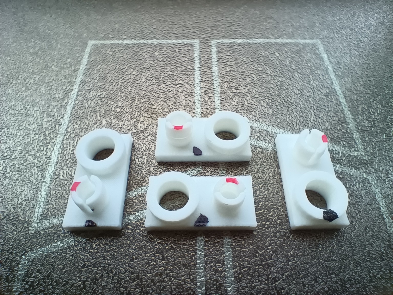
- the model is perfectly mirror-symmetrical from front half to back half, but printed normally it is always the front pin half that fractures, not the rear pin half.
- if you rotate the model 180 degrees, the same half-pin breaks, even though it is now facing the back of the plate
- if you rotate the model 90 degrees in either direction, the other half-pin breaks
- both pins will break at that layer with enough force but the pattern above is very consistent about which pin is much weaker than the other.
This has been repeatable over many test prints with different settings and different numbers of copies printed at once (from 1 up to 40).
Here is a photo illustrating the part and the behaviour. The black marker marks denote the part facing the front of the plate. The red marker denotes which half-pin fractured on squeezing. The part at the centre rear is the clone “printed normally” i.e. not rotated. For scale the base of the part is 8 mm x 16 mm.
This is the best close-up I have of the failure. (It’s difficult - it’s tiny.) It is a slightly different version of the part but the failure looks the same. You can see its appearance is consistent with poor layer adhesion.

The samples above were printed as follows:
- 3mf (saved from Bambu Studio so should have settings attached):
S0019.3mf (45.2 KB)
- A1 mini with 0.2mm hotend
- Bambu PLA Basic
- Standard settings for Bambu PLA Basic
I have tried:
- various setting changes (as prompted by AI) designed to prevent a change in layer time or in speed either side of the top of that tube on the right: it still happened
- having very long layer times for full cooling, by printing 40 copies at once: it still happened
- changing the height of the tube on the right: the fracture plane of the pin followed it up or down
- inspecting the slicing. The layout of the slicing of the two pin halves has perfect mirror symmetry.
- looking at the timing/ordering of the printing of each pin half and the direction the walls are drawn. I couldn’t pick up anything here that would explain what I’m seeing
The fracture itself is the problem but I figure the strange, consistent pattern about which half is by far weaker must be telling us something.
I’m new to 3D printing and would love some help with diagnosing and fixing this problem!
 &
& 