Well, I don’t know what you tried, so it’s hard to be specific. I did a test run through the process I was describing, which I’ve outlined below.
In Fusion, assuming you have a base object already, but I created a simple cube component/body.
Created a sketch with text paths on it. Also a rectangular outline to use as base for connecting all the text together. First extruded the rectangular base profile by 0.05mm and created a new component from that. Then extruded the text profile by 2mm and joined it to that thin flat base body.
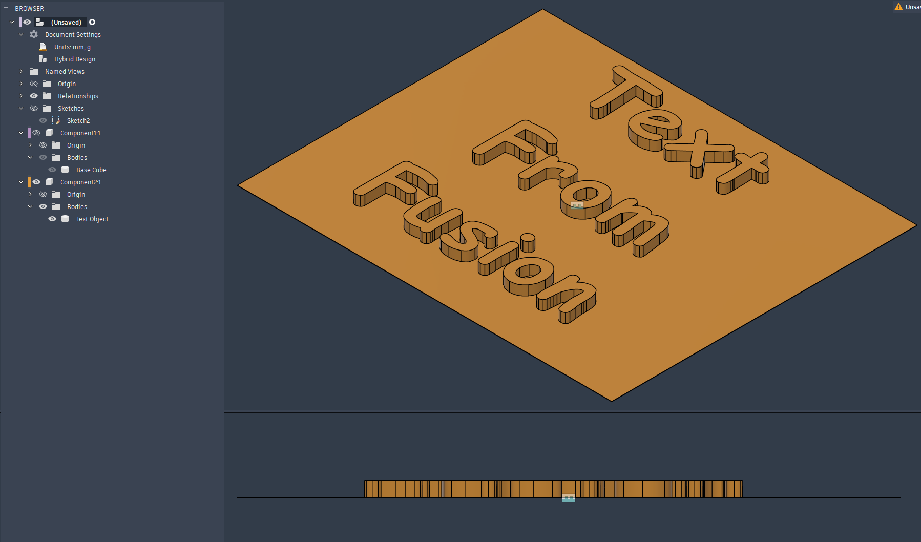
Then I created a joint between the base cube component and the text component, so that the top of the text is flush with the top of the base cube. I like joints and components, but you could also use position/alignment constraints or simply move bodies/components however you want them lined up. The point is the objects you want to export should be positioned in the Fusion design exactly how you want them in the printed object.
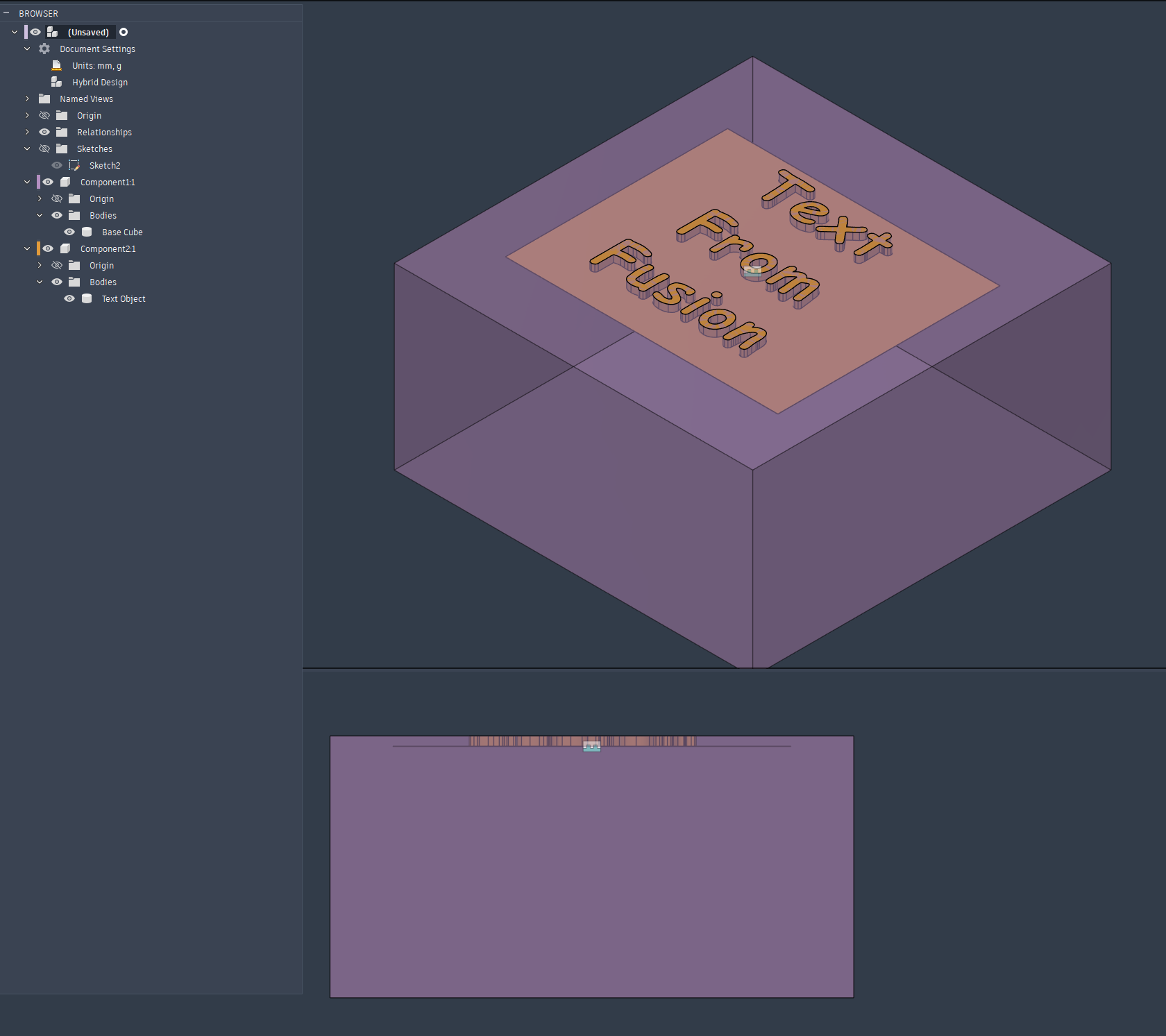
Notice how I named the bodies, inside the components.
Now make sure all, and only, the objects you want to export are visible. R-click the top-level document component and “Save as Mesh.” Select “3MF” format, single file *. Complete the export.
In Studio you can now import that 3MF file. Choose the “import geometry only” option that pops up. With Studio v2.5+ this will bring up a color mapping dialog box where you can assign colors to the bodies within the 3MF file… for now just Cancel that box (you can play with it later if you want).
In the next dialog it will ask you if you want to import the bodies as parts of a single object, choose Yes.
Now you should have one imported object in the tree with (at least) 2 sub-components, the base cube in my example and the text. And they should already be perfectly positioned relative to each other, as in the original Fusion model.
Make sure the text part is below the base part in the object tree. Or, as Eno suggested, change it to a “Modifier” type, which are always listed after the solid parts. For our purposes it doesn’t really matter if it’s a modifier or a “part.”
Orient the whole object however you want on the plate, in this case with text pointing down.
Assign distinct printing properties and/or filament colors to the text part, etc.
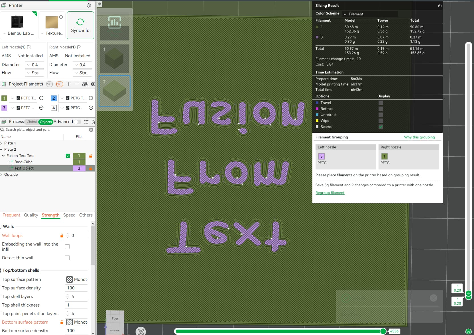
Not shown here, but that .05mm base plate from the text part is completely ignored by the slicer because it is so thin. Scrolling through the layers, there’s no sign of it inside the final print.
* You can also use STL as the export/import format, which may or may not have advantages in your workflow. The procedure is the same, except after importing to Studio, you have to r-click the imported object in the object tree and select Split → To Parts. Now all the internal bodies should be separate parts and you can proceed as before. The STL version doesn’t keep the Fusion body names though.
I’ve attached the test model I exported from Fusion, as 3MF. This is ready to be imported into Studio, as I described above. Also inside the .3mf is the original .F3D Fusion model I created. .3mf file format is simply a regular Zip archive – you can either change the extension to .zip and use regular system tools to open it, or open it directly with some archival software like 7-Zip. [I have to hide the F3D file this way because this forum stupidly limits the file extensions one can upload.]
Fusion Text Test.3mf (720.3 KB)
This way of working from Fusion (or any CAD) can also be used for things like modifiers, for example to reinforce some internal area of a model, like around screw holes. Besides being typically more accurate and reproducible, it also saves a lot of time when iterating a design, especially every time the “reload from disk” is not an option or doesn’t work and you have to copy and position all your modifiers onto a new object.
Anyway, hope that helps! 
-Max