I’m trying to print a tray with 4 screws to hold it up under another piece. The model measures roughly 60mm wide x 120mm long x 25mm high. It has 2mm walls and is hollow to hold lead beads to add weight to another project. The overhangs are tabs flush with the top about 10mm x 10mm. It’s printed with PETG. The final print looks great, however there is a thin line all the way around horizontally (barely visible) that breaks under stress. I tried printing it vertically, but I guess it’s too tall (it just seems to fall apart about 15-20mm high. Any ideas how to fix this?
I fear that we’ll need a few more details and maybe a pic or two to properly diagnose.
In general, PETG rewards having been thorougly dried and being printed slowly. I usually stick to 80mm/s but faster may be possible.
What you desribe as a thin line may be a “benchy hull line”. Where the bottom (and/or top) changes to infill, the large difference in layer time (check/post previews) causes uneven shrinkage.
If this is the case, consider a redesign with a chamfer around the base.
You may also want to increase the wall count since the part is load carrying.
 &
& 
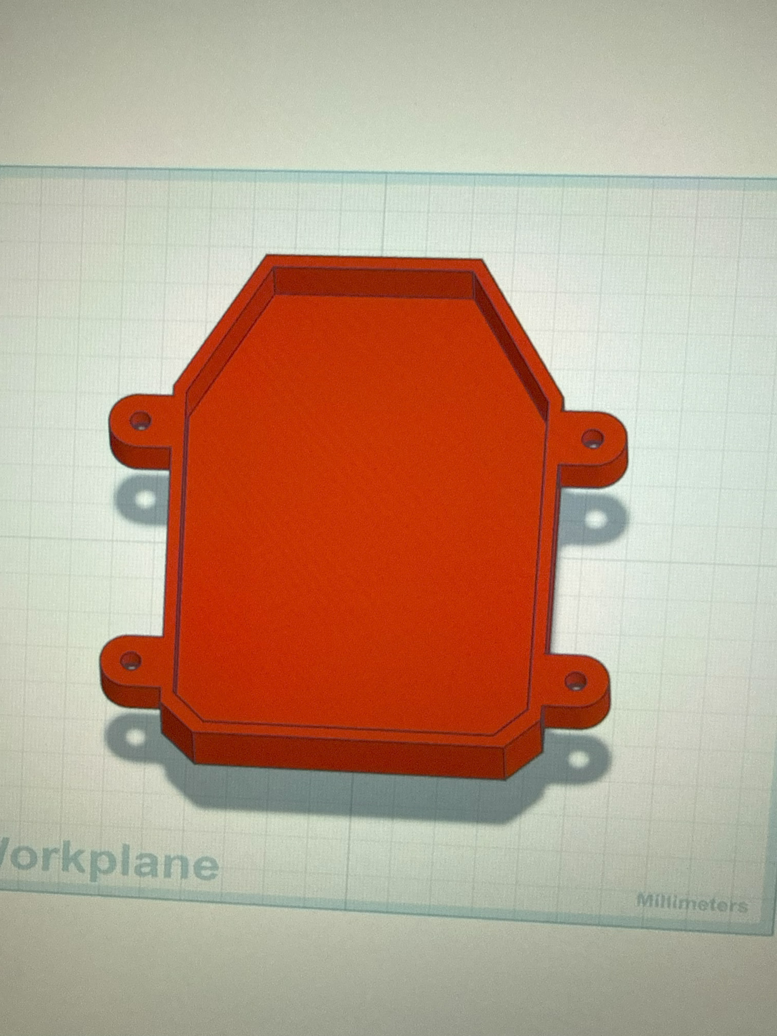
This helps a little, but there’s still no info on the failure.
At a guess, you are seeing the “benchy hull line” defect?
That can be improved by, for example, adding a generous chamfer to the inside.
&
What exactly do you mean by chamfer the inside?
Soften the 90 degree corner that the inside cavity creates on the bottom. Chamfer is often specifically a “halving” of the angle, and a single cut. A common other term is fillet, which is the same, but with a ball/rounding of the edge. Both will help accomplish “relocating the bottom surface farther away from the exterior walls to allow for some infill to sneak in” which helps relieve that stress
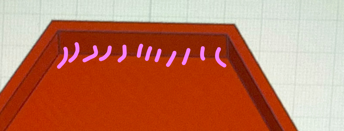
Tinkercad doesnt make it easy very often, but if that interior cavity is a “hole” object, redefine that “hole” object to have a border radius, and see if it does what youre expecting
Ok. I understand now. But it’s separating horizontally around the sides after print. I added angled support under the bolt slots, but that didn’t seem to help. I was trying to print with PETG and changed to PLA, but the same results. I printed with TPU for AMS and so far that’s working, but not sure how long that will last.
Well, aside from temperature, TPU is pretty much immortal so I would feel good about its robustness  Cinching up screws/bolts on tpu though is a little silly.
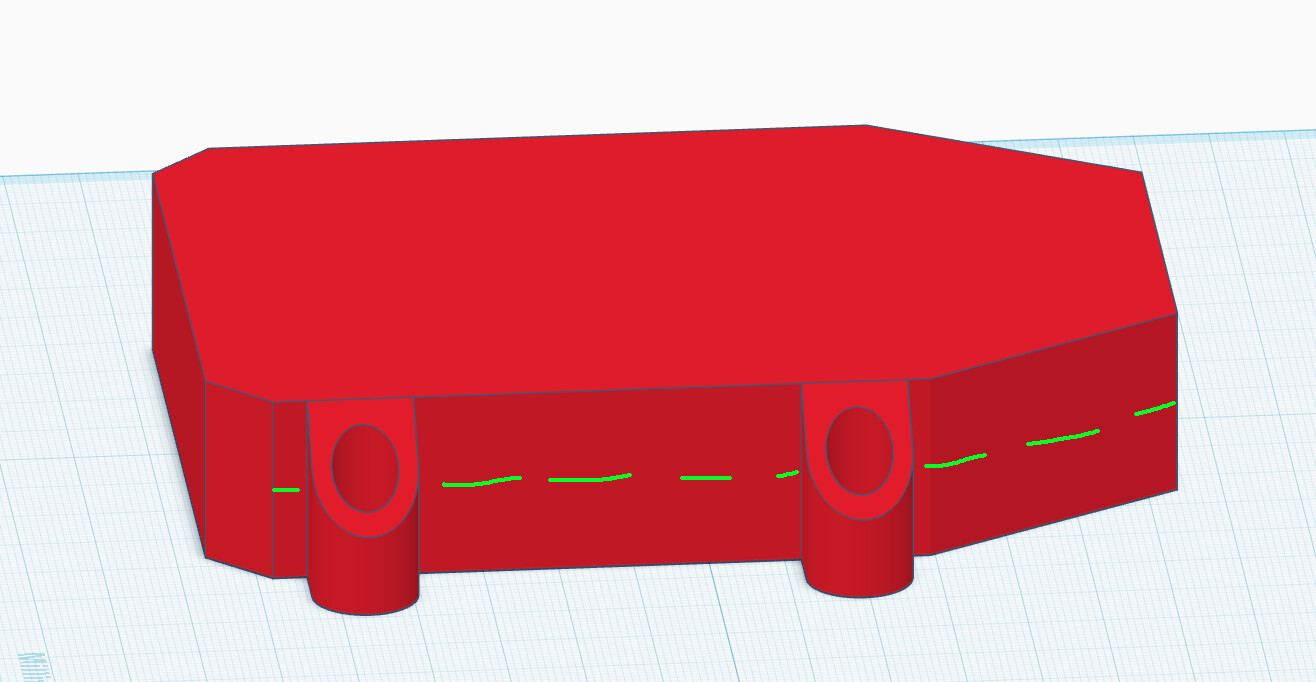
A pic of the printed object might help too, but I’m assuming that when you say it has a line all around and that it “breaks horizontally” you mean that it is breaking on the same plane as the box’s interior “floor”, +/- 1 layer from where the floor actually lies [measuring in Z]. If thats the case, then yes, all the various remedies for a “Benchy Hull Line” [mildly more googlable] will help you here. This specifically is a rabbit hole, material science is creeping in
That is why pic’s of the failure are important. If it does not work with (dry) PLA, chances are its not gonna work with other (dry?) materials.
Do you see warping in the PLA and PETG prints?
&
I do not have a pic of the broken part, I would have to print another.
I don’t remember seeing any warping. In fact, it looked pretty good. I just remember that when I tightened the bolts, it cracked. I pulled on it and it came apart.
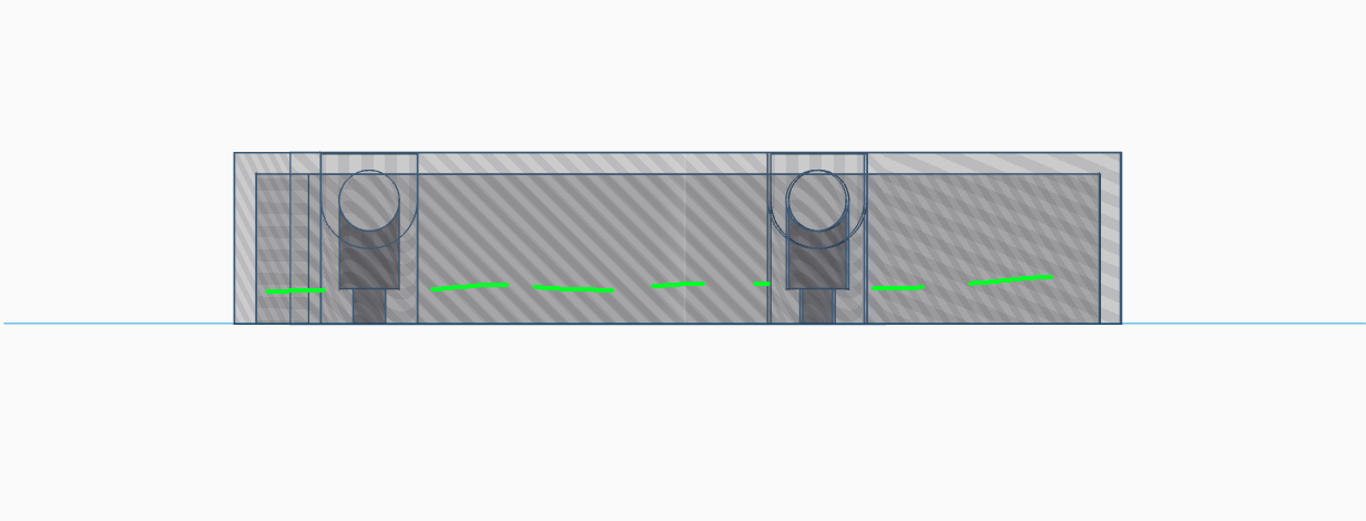
OK, that is in a different location than expected, but may be linked to the same root cause.
May I inquire as to how you dried the PETG and PLA? If you did not, that is one step to do as especially nes filament is frequently fresh.
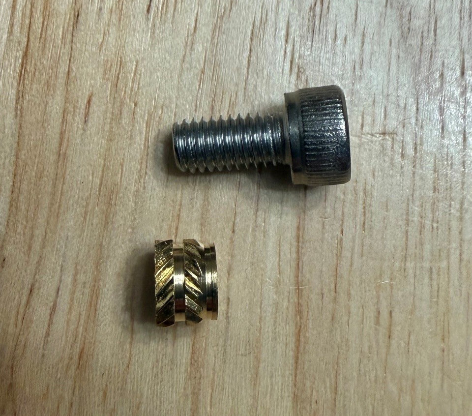
My next questions concerns the screws. What screws did you use? And into what material did they screw?
&
Seeing that screw X-ray helps, thanks.
Beware in general that overtight screws into most thermoplastics really like to creep out of the way, so finger tight is often the right tight. Going tighter now literally just loosens itself faster next month. If your drill has a clutch put it to lowest.
And make sure that’s not a conical-headed wood screw or you are perhaps aiding it’s downfall via wedge. It’s already weak in the z plane no need to make it work hard

Is there any interference with the thread or head? I presume that clearances are sufficient otherwise and you could try to further enlarge the holes (red) in order to gain some space for further chamfers (blue).
That’ll counter-act the mini-hull-line and help ensure that the screws only impart compressive forces to the print. Shear along the layers is almost as bad as peel loads 
I think all the tolerances are good. I’m not sure what shear and peel loads refer to, but I’ll look it up. I’ve noticed in some of my other prints that there is a horizontal line and overhangs and landings for screw heads (pardon the language, but I’m not savvy to the shop talk).
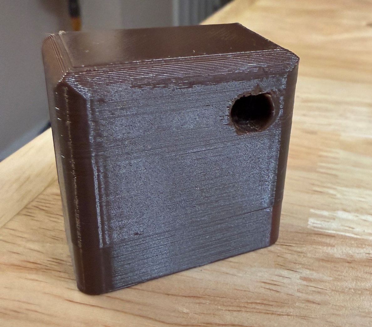
Below is a picture of what I mean. This piece has a screw hole in the bottom that is countersunk to the place where that horizontal line is.

No worries.
“Shear” describes scissor like loads. Imagine two load planes running left to right Like one printed layer above another. Scissors impart loads from one direction into one plane (layer) and in the opposite direction in the other plane.
“Peel” is just as the name suggests with these two load planes. Rather than along the load planes, it pulls the planes apart. Like peeling an orange.
When putting a screw into a hole which is locally slightly smaller than the hole, it results in shear loads. So it is usually a good idea to design for clamping only by leaving plenty of space in the upper part for the screw to travel through and only “bite” in the lower part.
Those hole defects are unfortunately very common in non-vertical FDM. They result from overhang performance and bridging.
To overcome this, FDM designers are currently and frequently using non-circular holes. Common are
- a teardrop shape where the upper part of the circle is replaced by a little roof at an angle that fits the overhang performance (45° is pretty safe for FDM, 60° is doable for PLA).
- A Hex hole
Threads are not usually modelled as the part to be attached typically relies on clearance while the lower part the screw cuts into often relies on the use of thread cutting screws (lots of walls in this location) or heated inserts.
&
I’ve tried the tear drop and it works pretty good. My concern is the separation. Could it be nozzle temperature or something to do with bridging. If so, where are those settings? I’ve started using Orca slicer and the only bridging setting I see is in percentages. What should I use as a percentage?
That line at the lower end of the cube is probably due to a slightly longer layer time from the additional surface at that height.
In this case, you are likely able to improve it by changing the hole end, which acts like an internal bridge during printing, from a flat bridge to a 45° roof by adding a chamfer.
&