I assume this is probably not an original idea (or it doesn’t work for some reason). Is there a way to shorten the max length of bridges by using multiple layers for bridging instead of a single one?
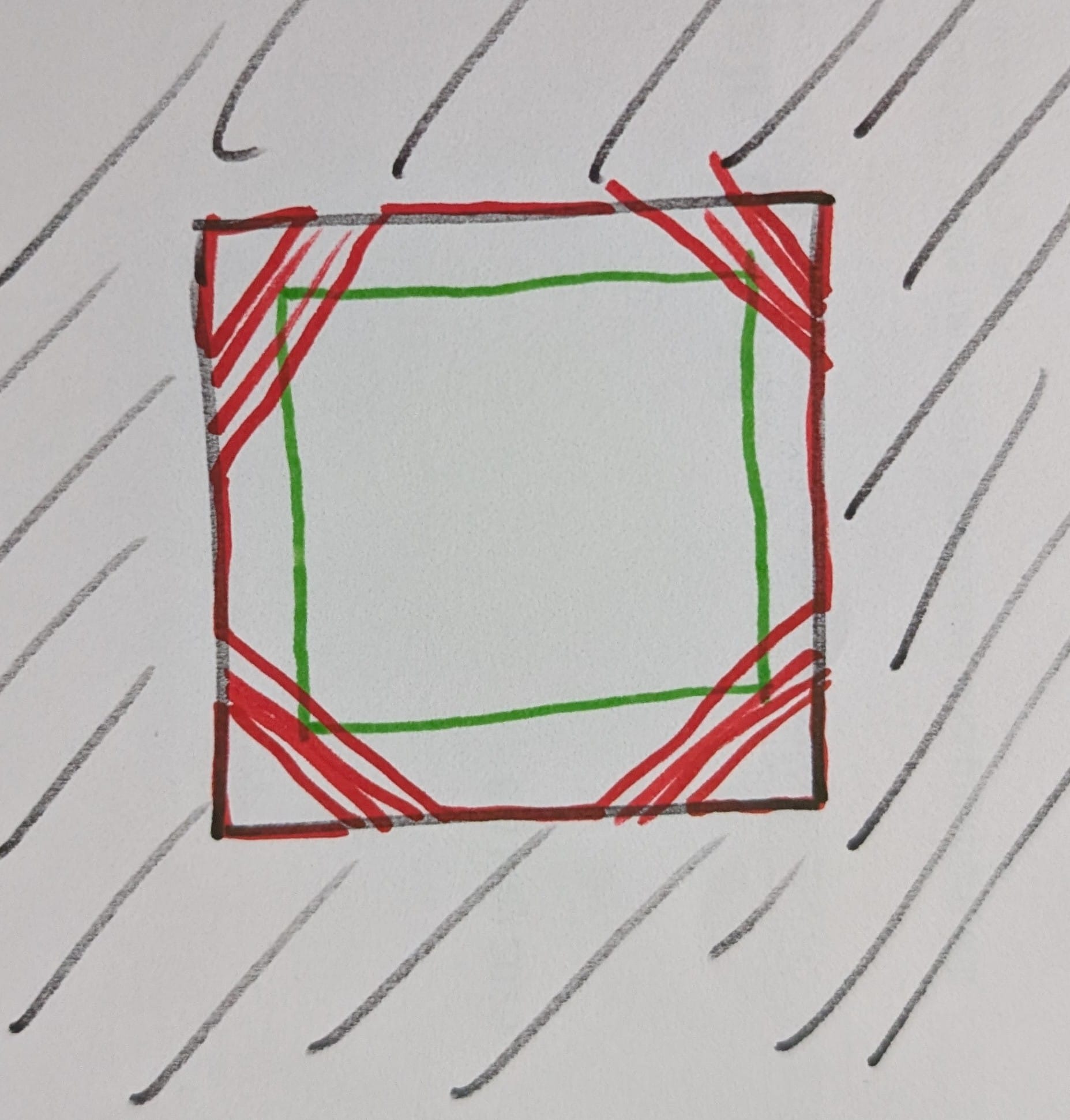
For example, in the attached image, instead of bridging the whole black square, the slicer could create the red layer, which demonstrates (in green) that it can be used to reduce the size of the original bridging area. There are probably more clever ways to do this, but that’s one way.
Of course there’s the downside of changing the piece, so if it matters to you that the “ceiling” should be “flat”, this setting wouldn’t be helpful; but if you’re printing a functional part, this could be useful.
With the slicers job being the path generation for any shape thrown at it, any change to the actual geometry is (usualy) best done in CAD. @lkraus post says it all really
Well, to be fair, with boolean manipulation, scaling, cutting,… there are already a few basic CAD features in slicers.
This is a bit different in that it changes geometries based on manufacturing improvements. So it could very well be a useful feature.
However, you can already implement this through geometry changes in CAD or using CAD imports as negative parts to make the neccessary geometric changes. In that manner, you can try out your idea and see where it leads.
I dare say it could be particularly interesting in combination with adaptive layer lines.
")