Hi there, new to the forums and relatively new to filament printing as of December, though I have been doing resin printing and designing for a few years now.
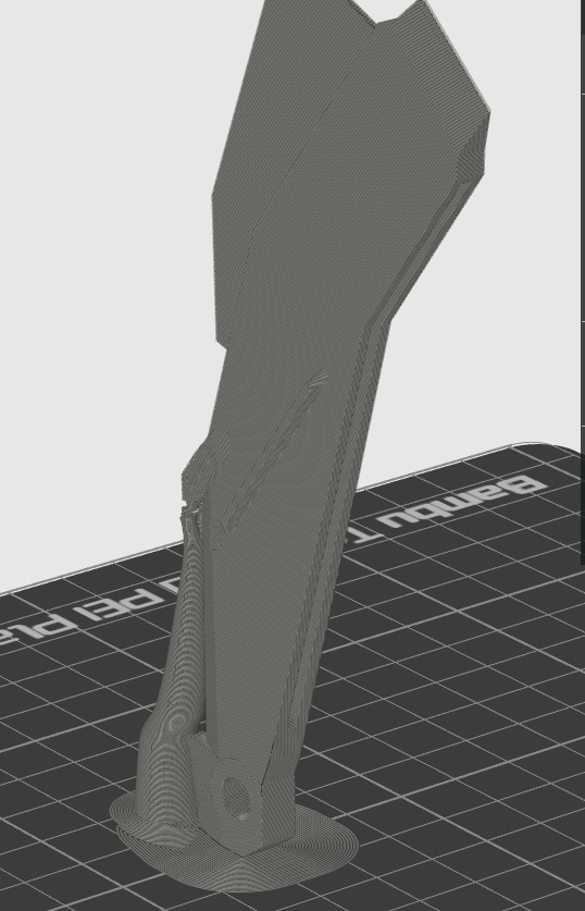
I’m trying to figure out why a part I have seems to develop geometric depressions (either that or there are bulges in the print outlining a shape?) in a part I am trying to print.
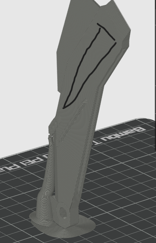
The part in question has a cutout from the back-side of the part, and the depressions occur in the walls parallel to the cutout, roughly in the area marked in the screenshot below as well as on the opposite side of the part The surface of the part should be flat, so the depression is not intentional. Sharp corners on the part are also bulging outwards/rounded slightly, so I tried addressing this in case it would resolve the depression. I have not been able to prevent either.
I am printing the part vertically like this because it wasn’t really originally designed for filament printing and I am just experimenting with what I can do (in other words, there aren’t many good surfaces to put flush to the base plate), but the depressions only started to appear when the cutout was made (so it can interface with another part). I have to assume it is related to how the thin walls are being created.
What I have tried so far
-Printed with the preset Bambu .20 mm standard profile, slightly modified to add supports and use arachne wall generation. This is represented in the attached .3mf and is what I usually use
-Printed the part at 105% scale to see if a slightly thicker structure changed anything (no change, just bigger).
-Tried running manual flow dynamics calibration and re-trying(k value slightly changed, and if anything print quality worsened)
-Tried running manual flow rate calibration (no change in settings due to the calibration)
-Printed with the preset Bambu .08 mm quality profile (the effect was somewhat less severe but still present)
-Printed with the default Bambu studio settings, which as far as I can tell have MUCH slower acceleration and speed (no change)
-Printed with the preset .20 mm standard profile and standard wall generation instead of Arachne (no change)
-Printed with outer/inner wall generation instead of inner/outer (This seems to have just shifted the pattern outwards, so while there is no depression the bulging surrounding the depression is more prominent. There is also more bulging elsewhere on the part)
I’m running out of ideas as to what might be causing this and hoping the kind people of this forum can set my head straight as to what might even be causing this. The printer is working great otherwise and I’ve done some cool stuff with it, but this issue is sticking. Even if the part itself just isn’t fit for the medium, I’d like to at least understand the why so I can avoid it going forward.
I noticed there seem to be layer lines on your filament. Is your filament dry, or has it been in contact with moisture? I also notice that there are very few supports on your build plate, perhaps increasing those will lower the stress on your print? Regarding the main issue, it seems to me as if you are talking about the little V-shapes… is this correct?
This is a P1S with the standard .4mm nozzle, and AMS.
As for your questions, in order
I do not currently have a filament dryer, but I have been doing my best to keep it dry. My printer setup is in the basement of a home that was in the middle of a cold, dry winter, and I am using an AMS with silica-bead-holding spool weights to keep things inside the AMS as dry as possible. So I can’t guarantee it is dry, but I’ve been doing my best. To my eye the layer lines (with the exception of those in the problem area) look worse than they are in that image due to zoom and lighting, though I could be wrong.
I am using the auto-generated supports that Bambu studio suggested. More supports might be a good idea, but I’m not fully sure what forces I am supporting against, other than overhangs.
Yes, the main issue is the sort of V-shaped area composed of bulging print lines and a slight triangular depression inside that V
Bambu Studio does a good job with support generation, so we can check that off. Regarding your detail… it seems to be like a moist filament issue. I have printed an entire costume with my printer, and there were some hefty parts in that load. I never once had a layer line issue. I have the AMS 2 PRO with drying capabilities, so my filament was dry.
When was the last time you ran a full calibration on your printer?
RE: full calibration, that would have been about two months ago when I first started with the thing. But some of the parts of the calibration (ie, bed level, vibration check) are done automatically before each print, and I did manual calibrations of the flow dynamics and rate settings.
I’m able to print things with other geometry alright (I get slightly rounded corners on those too, but not this major bulging/sagging issue). It’s just this one shape that seems to encounter this.
I just looked at the 3mf file and have a general question: Why are you printing it upright? The higher you print, the more likely vibrations are to become noticeable, especially at extreme heights with an extremely narrow design?
Wouldn’t it make more sense to approach it this way? You can still go over the surface with a file afterwards to make it perfect; this is not noticeable with white filament. Perhaps very hot water will suffice, too. Or if you’re brave, use a hot air gun, but please be careful! Quick and straightforward.
If you print it this way, put it in the freezer for 5 to 10 minutes along with the printer plate. Then you can remove the support more easily and cleanly.
Furthermore, for such extreme requirements, you should not use the standard 0.2 profile, but rather a “High Quality” profile and start your settings from there. Because the speed of the printer is reduced. What you did great and is important: Gyroid, perfect!
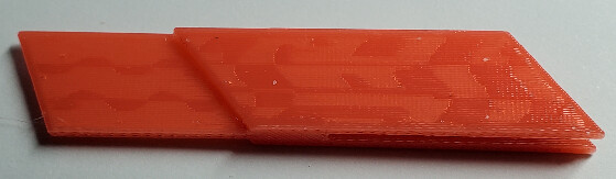
However, I would set the wall thickness to at least 3, as 2 is insufficient in this context. Just look at how fragile it is with only two walls:
This probably won’t solve your main problem, but it will significantly improve the quality. Poor-quality settings and problematic orientation also contribute to the issue.
In short, I believe the main problems are vibration at high speeds and the extremely thin tall construction. With the standard profile, the speed is probably too fast, causing it to vibrate. It’s not as extreme as it sounds, but it’s enough to cause mistakes.
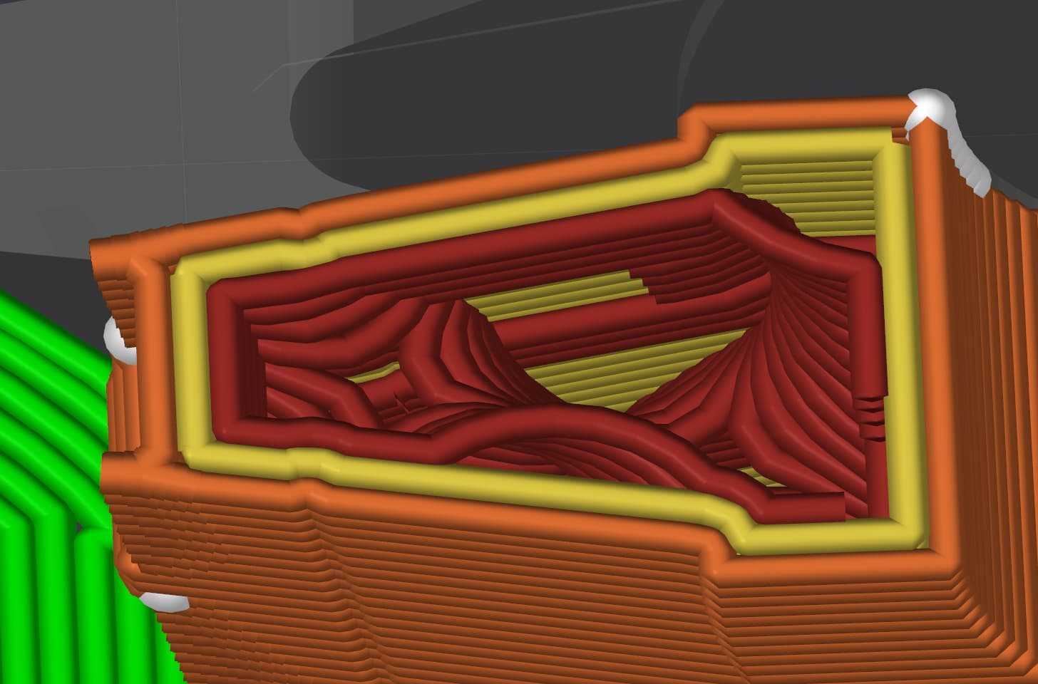
The outer surfaces of the part are tapered, allowing more walls at the outer edge than at the beginning. The bulges occur at the transition between three and four walls, and at the end of the slot.
Try combinations of a smaller nozzle with a narrower line width, or thinner walls. The part is not very thick, so your options are limited. Thinner lines may just create more, less noticeable bulges at different locations. If a single wall is strong enough, the surface may be smoother because the overall thickness variation will take place in the infill, but the infill may show through.
Well, 12 hours of drying and a quick print later, the overall quality I think slightly improved but the issue persists.
The change in wall thickness absolutely makes sense as to what might be causing this, thank you for the suggestion. I’ll play around with it when I have time and see what happens.
I think ikraus identified it right, and if you can fiddle with the Arachne wall sizes enough, you might be able to get it to use full independent wall loops through that whole area. This will prevent the extruder from having to retract and travel to get to the next spot, which is likely causing some of that effect. You will be able to see this in the preview.
Just following up, Ikraus hit the nail on the head. It was absolutely the change from two walls to one solid infill. I’m gonna go play around with settings more, but a test where I knocked it down to one slightly thinner wall made the issue go away. Thank you!
This sounds silly, but it works. Power off your printer or even unplug it for one minute. The run a full calibration in settings (the long type that takes 30 minutes) Then run the short generic type. Try printing again.