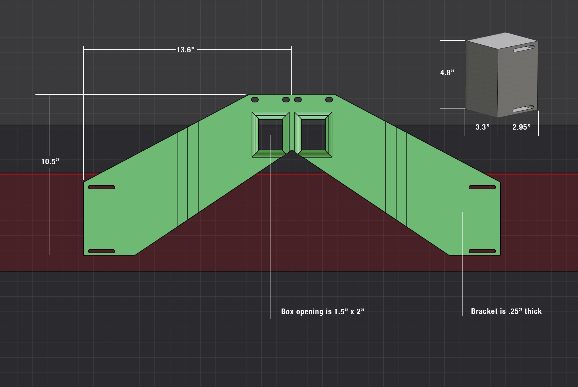
Here is a 3d view of the project to print out brackets to hold a KEF XIO soundbar which weights 20 lbs. The green brackets L&R are printed in two pieces and the grey is an extention to place the soundbar infront (Red in view) of the tv (White in view) ,
So my questions are what is the best orientation of the green pieces on the build plate for greatest strength and what infill and density.
For the grey etensions is it best to print them as part of the green bracket or print separate and bolt to the green bracket (the soundbar (Red in view) attaches to the front of the grey extensions, so concern about stress of the soundbar on the brackets
Lets say filament is a new roll of PLA, green parts have three bolts as illustrations hows and all things concidered is it be to fuse the grey parts to the green or print them seperate and bole together.
And at the least what orientation on the build plate for greatest strength no matter what filament is used.
I’d be more concerned about the stress of your TV on the bracket, or is your TV already mounted on a VESA bracket? And mount your soundbar separately and closer to the wall. Didn’t it come with its own bracket, or at least holes in the back to hang it on a set of screws?
The green parts: I’d print them with the front of the TV side down. That makes it both easy and allows for the XY plane to take the brunt of the stresses.
The grey bits: they’re less loaded than the green IMHO, and I’d just print them upright as they’d get installed.
Material choice is however VERY important. I’d avoid PLA as it doesn’t like prolongued stress all that much. Moreover it also dislikes humidity and UV light. I’d go for PETG-CF, ABS-GF or even higher, esp for the green part.
Which brings us to the design: hanging ~10kgs extended to the front off of that green part might not be the smartest move without strengthening the green part against the torsion it’s going to get. Some fins added to the rear would go a long way to achieve that. If you can: leave out the grey bits: it’ll be much more gentle on the green parts itself and its attachment to the TV (which will also need to carry the stresses).
thanks so much I didn’t think of fins on the wall side. this bracket will mount to the wall mount f(and back side of TV) for the tv which extends out 2 ft form the wall when we are watching it and the atmos aspect of the soundbar needs to be in front of the tv., hence the grey extensions
I fear most for the way the green part is connected to the TV: the 10kg weight has a lot of leverage on that small part. Obviously I don’t know the dimensions of it all, the TV’s construction, nor ability to deal with that, but extending it forward gives the weight leverage to try to pull the green part backwards.
Just my intuitive engineering spots it as a likely weak point. I can’t do any calculations with the data I have, and getting the needed data from the TV maker isn’t going to happen anyway.
If you can make the contact surface between TV and green part extend further up (assuming the TV’s surface can handle the forces involved): that would be better.
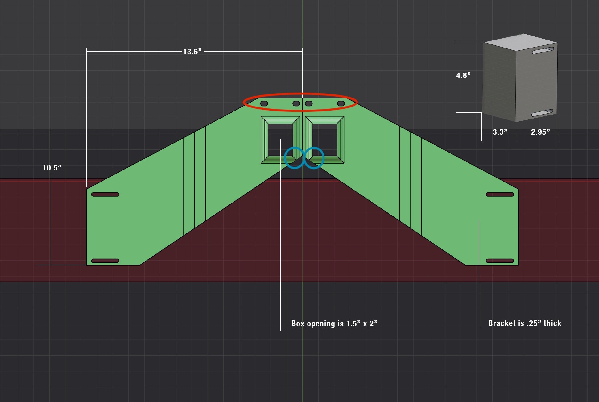
Similarly the green part near the top: add fins as the momentum it needs to sustain might be too much, esp with those large square holes you have there as well.
[Sorry if my vocabulary in English is lacking when it comes to material and strength - it’s been decades since I was an engineering student and I was taught it all in Dutch - trying to translate it makes me feel like an amateur]
the tv mount can hold the weight of the tv and the soundbar the sq holes on the brackets are because of an obstruction from the mount (for our existing Bose bar that attach to the tv wall mount so the new soundbar is not attached to the tv but the wall mount, the measurements of the bracket are in the new illustration attached hope this helps and thanks for your insight
The red area: that’s where the torque of all of the weight hanging in front of it needs to be absorbed in a very short distance. Try to increase that vertical distance if at all possible.