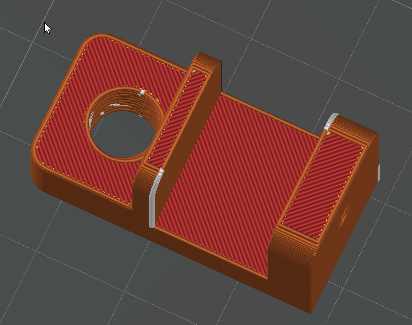
This is my first foray into 3D printing. I have an X1C and created a little bracket in Fusion 360. I printed it with Bambu PLA-CF, and it turned out fine. I do have some questions. The big hole in the bracket is an M8x1 threaded hole, and the little hole is a 6-32 screw hole. Are these too small and fine for 3d printing? The needed items were screwed into the bracket, but it was awful tight. Is there a tolerance that needs to be set for bolt holes?
Second, the slicer has white areas; these are called seams, and the cross-hatched red area on the legend is labeled sparse infill. Should I be worried about this?
I do not have problems with screws in printed parts.
You may need to tweak the size to fit depending on your material.
The white seams are normal. When the line begins it starts extruding and then moves to the end of the line. The start and ends blob slightly because they haven’t moved or have just stopped, causing a fraction more material in those two spots, thus is the seam. The scarf option can minimise this, choosing where to place the see, can help improve the appearance if it is a concern. Experimenting is the best thing so you understand how best to work with your design.
Sparse infill is simply the name for infill. Sparse meaning it isn’t meant to be solid often. The amount of infill is based on the percentage you choose and the pattern is your choice, different patterns can increase strength, reduce material and even speed for model is that will never be handled.
Experimentation is king here as well. Experience will teach you to balance the number of walls, infill percentage and type of infill depending on the type of model and its needs. Strength is often a key factor, the more surfaces a model has can also increase the strength. A cube with a cylinder going through it is far stronger than one without. This doesn’t mean you should, it just means added surfaces increase strength.
I would say yes, you need to account for some tolerance in screw design. The M8x1 should be fine for printing. I did an M10x1.5 and originally just scaled the x-y a few percent down and this worked ok but did have some binding still so I investigated other solutions.
The guide I ended up following was:
Fillet the sharp edge of the screw thread to round it over a bit, not too much, threads still need to thread. Can’t remember but 1mm sounds about right, in my case that was 10% of M10.
Select one of the thread faces of the screw, offset face ~0.1mm, repeat for other thread face of the screw.
6/32 is getting a bit small, depending on the functionality I would decide if it would work with plastic or perhaps a heat insert should be used, or maybe you intend to use a normal steel screw into the threads which will work for limited mileage.
I’ll share a couple of tips I learned along the way with respect to making structural parts with thread or bolt/screw holes that have really helped a lot.
You will eventually stumble upon heated brass inserts. They are very nice for making parts that need frequent disassembly such as the lid to let’s say a battery enclosure where wear is an issue. The downside is they take practice to install correctly and they take up 2-3X the diameter of the thread hole being accommodated.
You can make can cut threads directly into the plastic with a tap. However, PLA is often too soft for smaller diameters holes. I tend to use PC filament for this purpose at high wall density which comes out out very structurally strong.
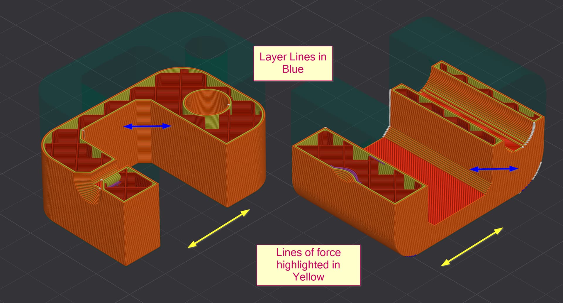
Remember that layer lines are the weakest point. So you will want to do the following in your design.
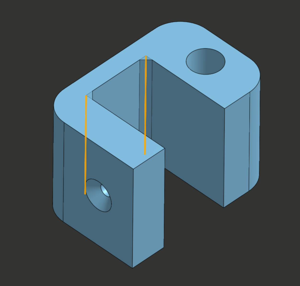
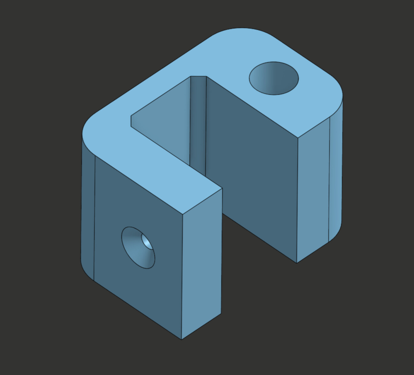
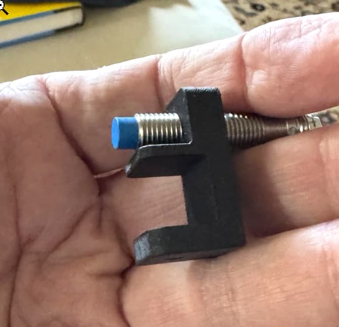
Use chamfers in your design wherever there is an edge with a stress point. The model will want to break at sharp corners and the chamfer will spreads out that stress. Alternatively, you can use fillets for appearance but chamfers work better. Here’s what I mean using a bracket I created for a wood shelf I was reinforcing:
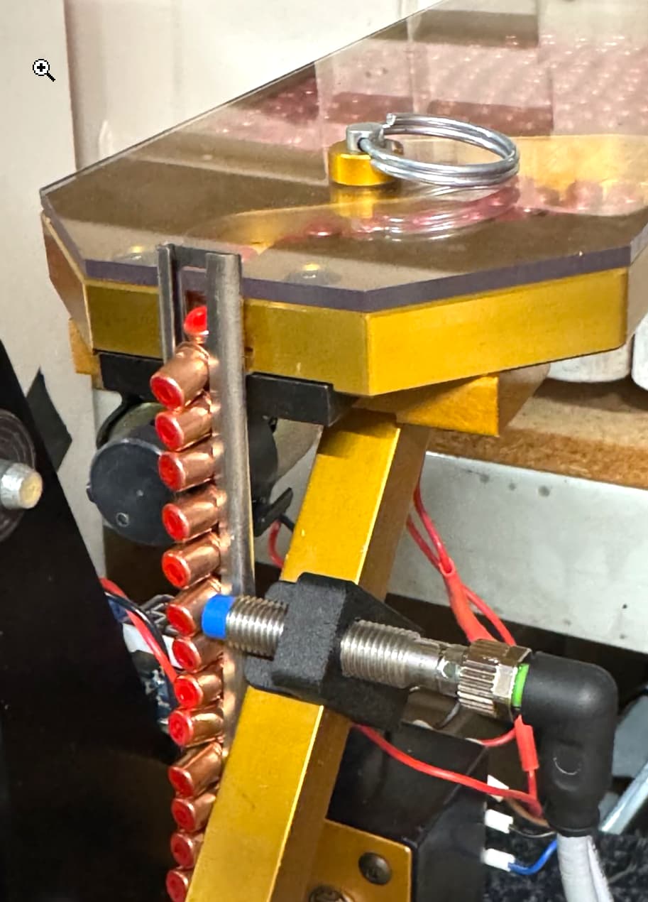
Depending on how you plan on stressing the model, you will want to orient it on the build plate to take advantage of the layer lines. The model on the right will be able to take more stress when clamped onto a surface because the layer lines will be vertical whereas the model on the right will be weaker because the stress will be in the same plane as the layer lines. Chamfering helps but will not solve all problems.
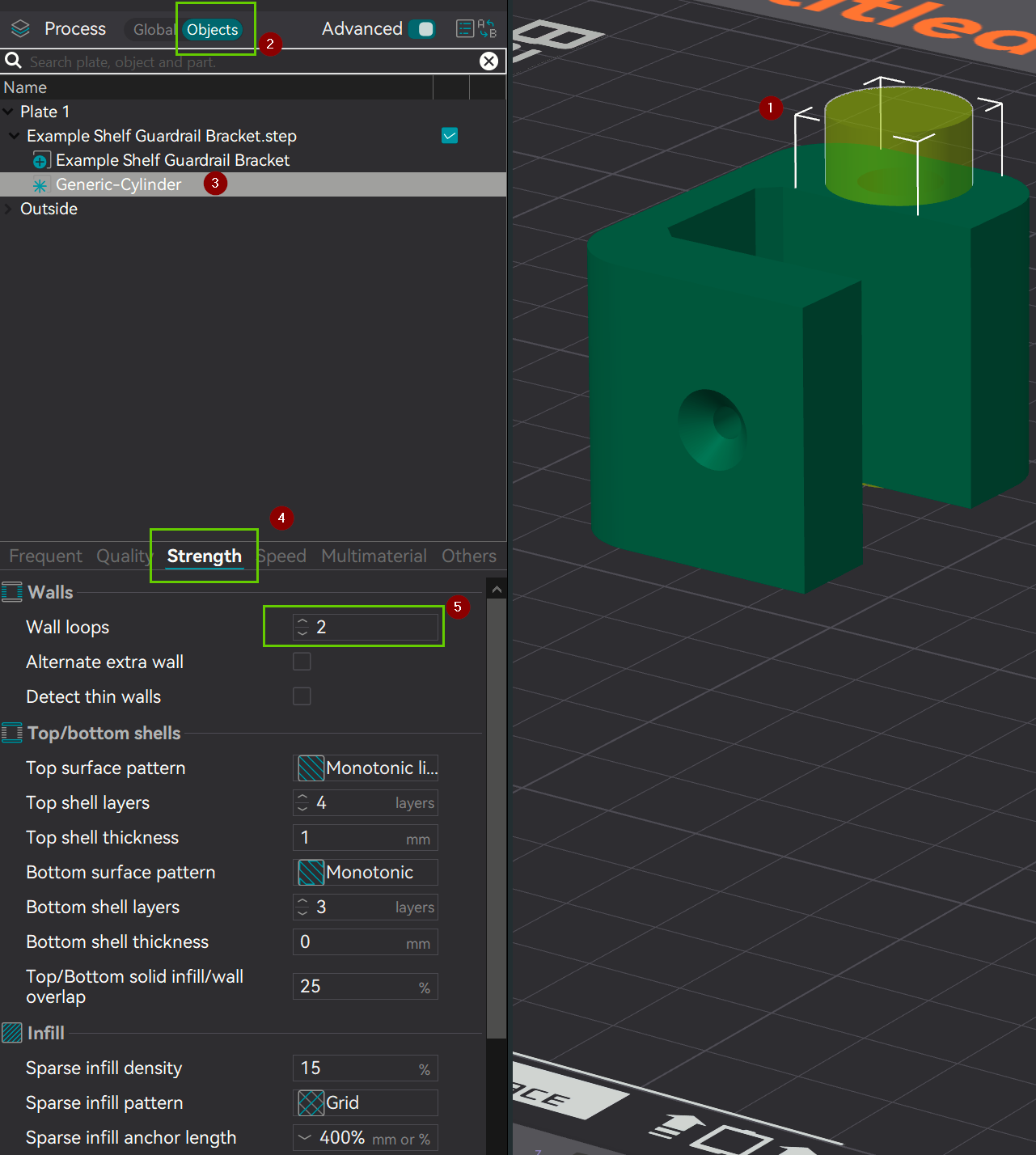
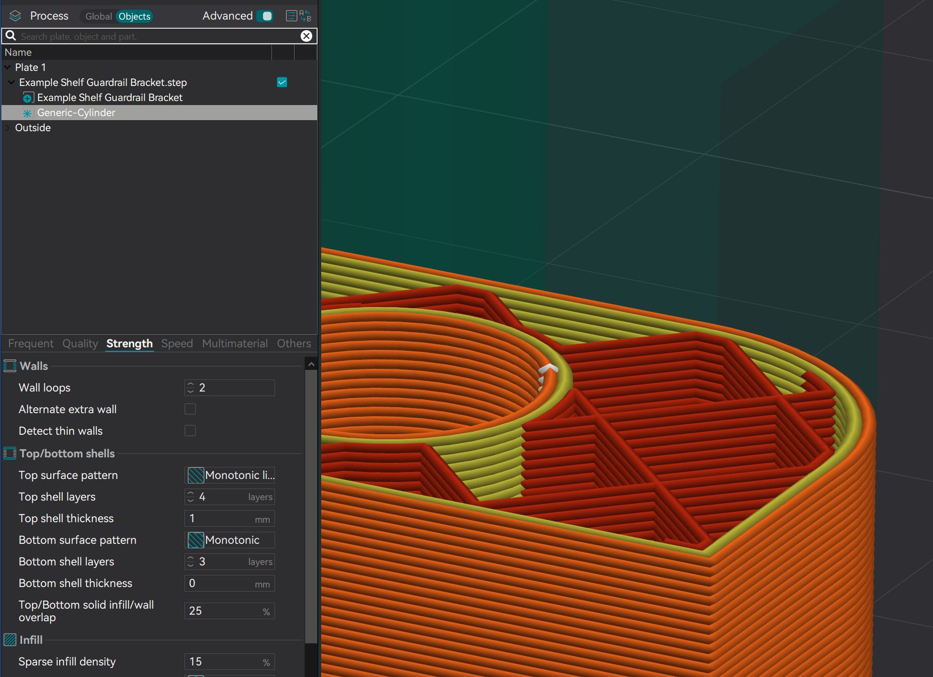
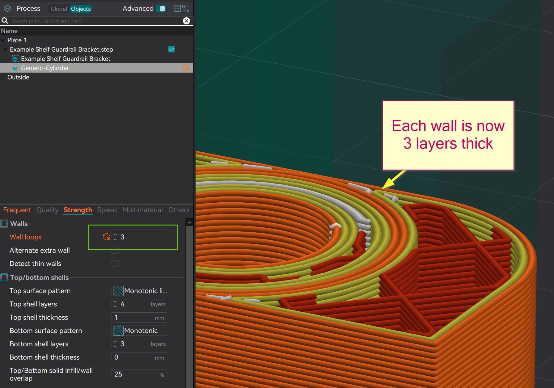
Last but definitely not least. You’ll want to master modifiers around the holes. You’ll find that you can increase the overall strength of the part by increasing wall loops in favor of increasing infill %. However, you don’t need to do that everywhere. You can use modifiers to tell the slicer to do this for the holes only.
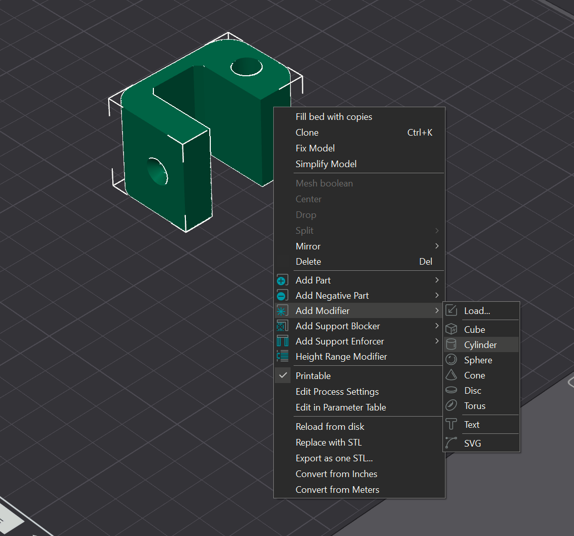
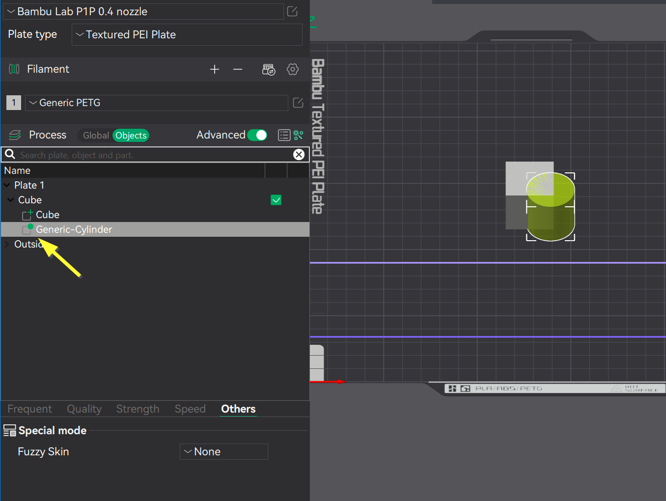
Right-click the model select modifier and select a shape–cylinder in this case.
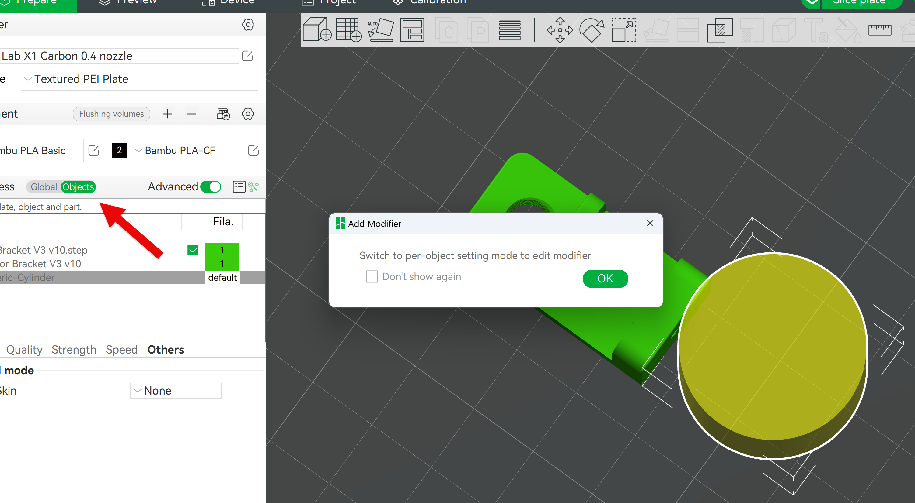
This will thicken up the hole-only and make the slicer reinforce the hole so that it can accept threads more easily or if you’re using self-tapping screws, give it more material to bite into. Click on image to zoom
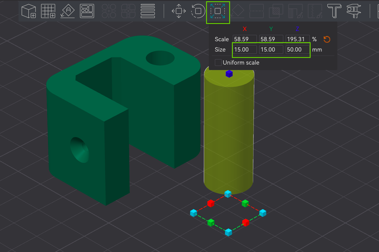
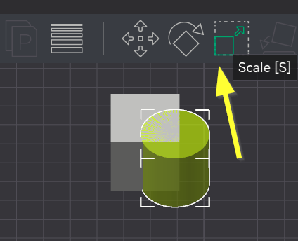
Once you click OK to the popup you will be in object mode with the cylinder selected, from there you can scale it and change its printing settings using the object mode as @Olias showed.
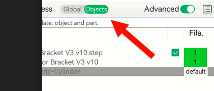
You did ‘add modifier’ with the bracket selected correct? The will pair them in the object viewer.
That error message makes me think that you have two separate models that are not part of an assembly but your screengrab is clipped. If you can you upload the 3MF file so I can take a look? Or simply grab all of the screen so we can see what the object context was. The arrow here points to important Icon information which will tell us what the slicer is being told to do. Your screengrab is clipped.