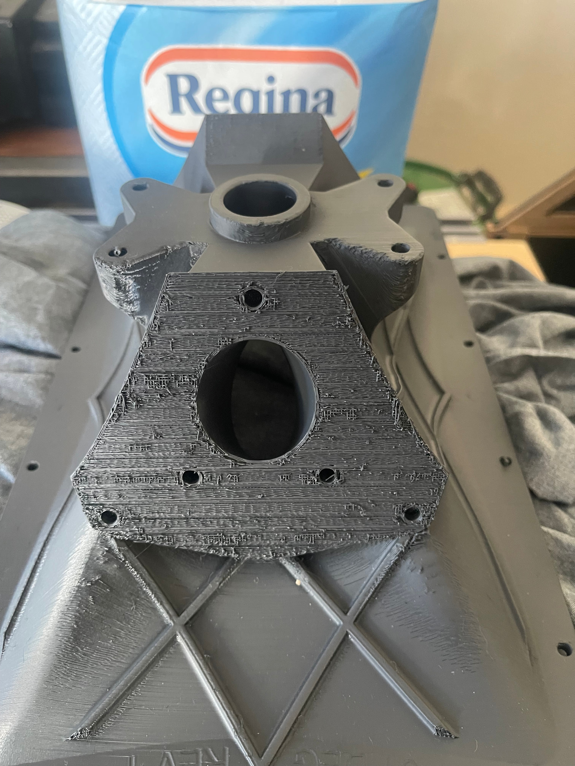
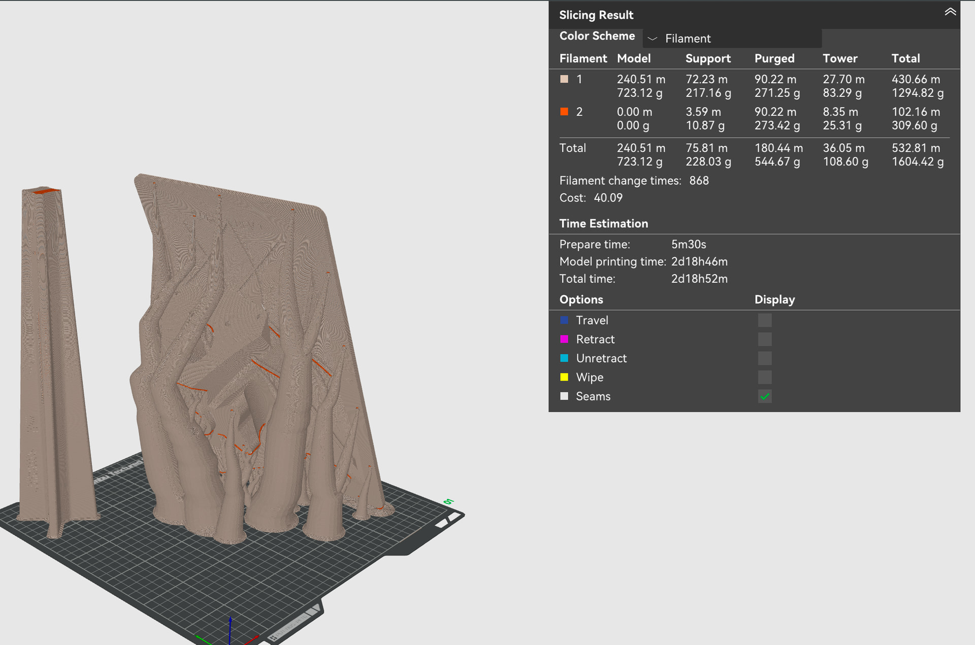
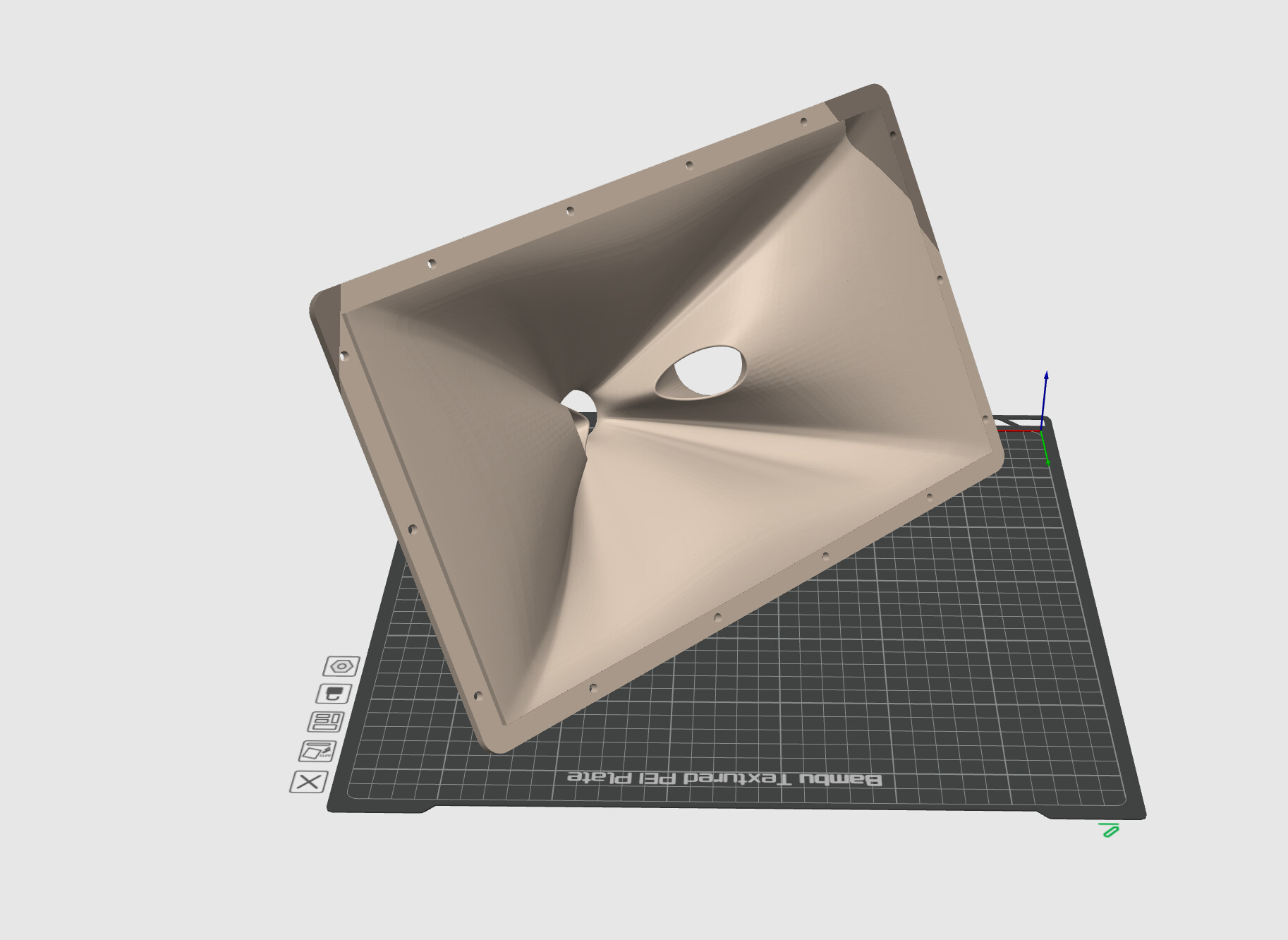
I have only had my H2S for a couple of weeks and only used PLA basic and Petg basic so far but having trouble with poor quality on overhangs. I have tried strong and slim with various advice from AI but results are still not great.
Are there any ways i might try to improve this or is this to be expected?
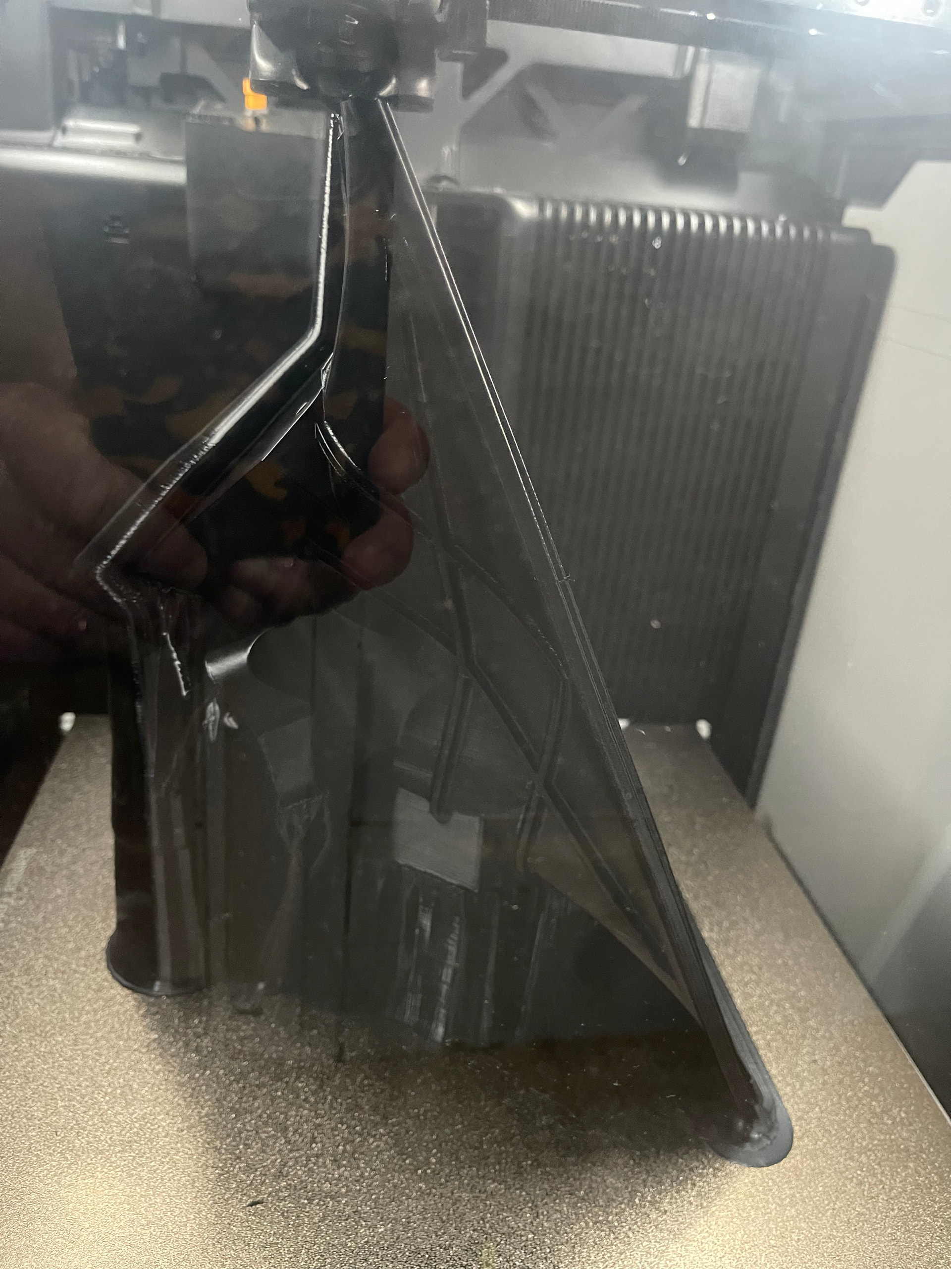
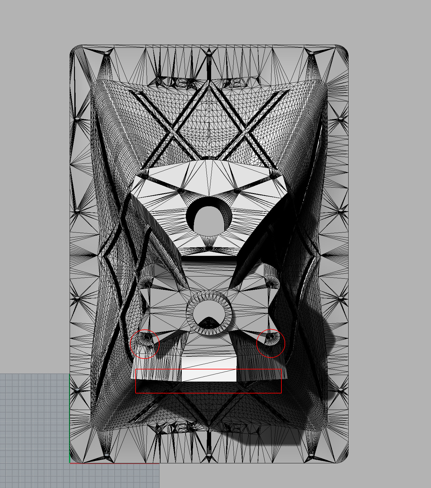
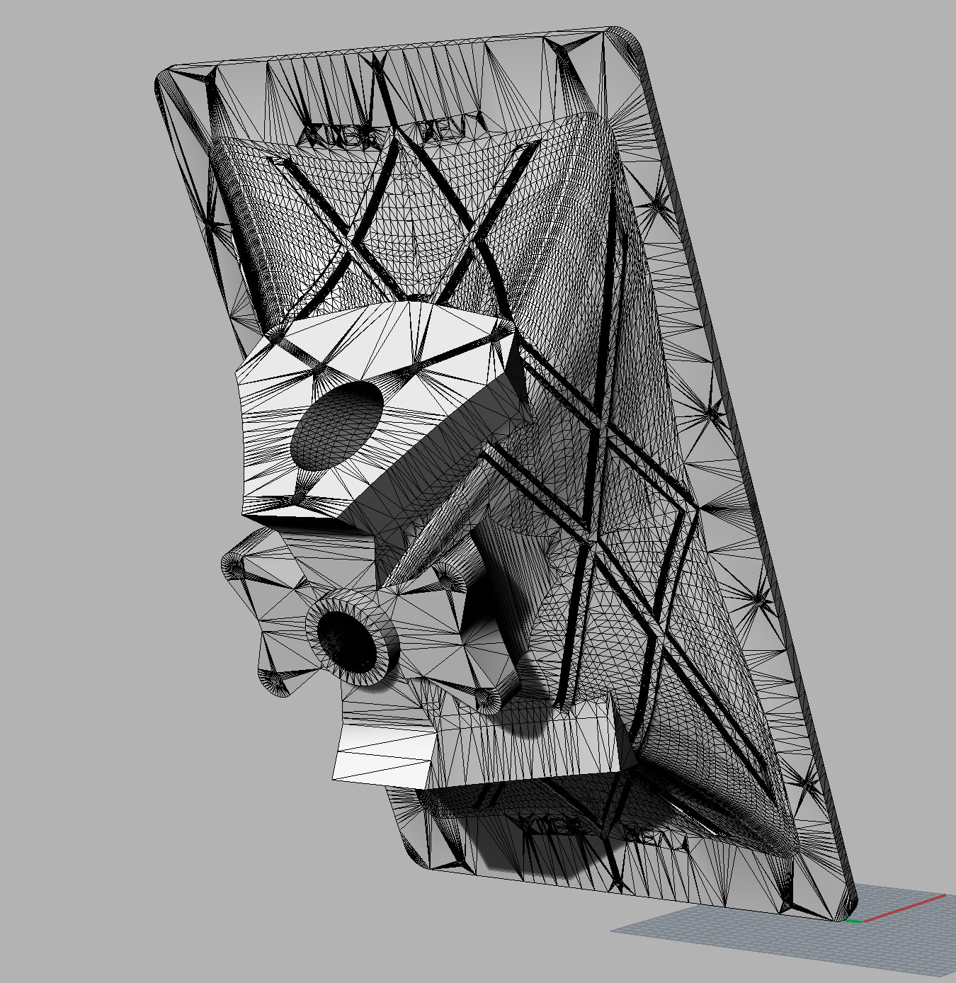
How steep are those overhangs? I have difficulty to relate orientation of the finished part to the picture in the printer. Maybe you can mark some of the features on both pictures?
Ah, maybe I get it now: The big flat area is almost touching the build plate?
Then I would say, this might be as good as it gets without support interfaces in a suitable support material. Maybe you can tilt the part a bit more, so that the big surface is parallel to the build plate? That would probably make it better than this very light slant. If you have an AMS, it would also allow to use PLA as support interface on just 2 layers, so with minimal filament swaps.
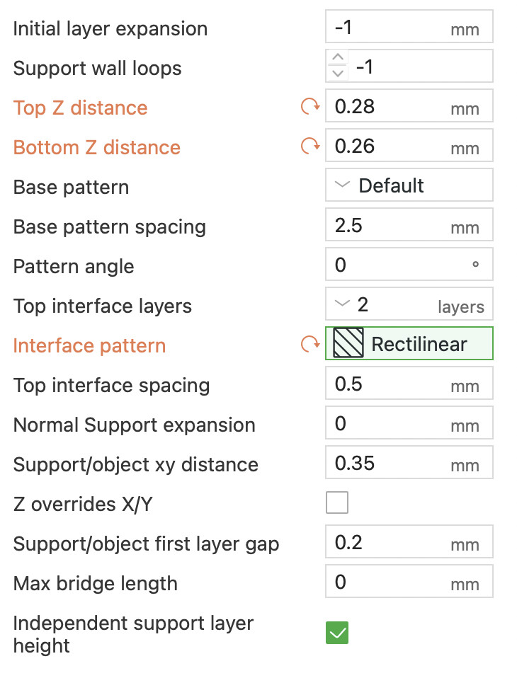
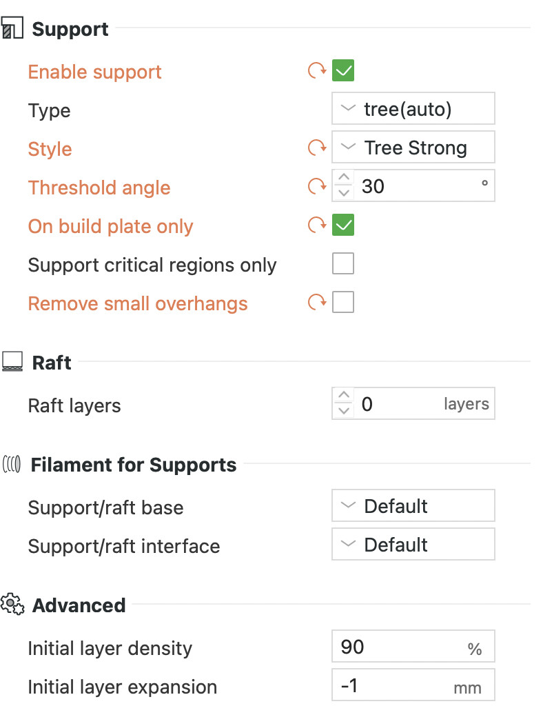
What do your support settings look like currently?
perfect, now it is easy to understand.
I think the 30° overhang threshold are asking a lot from PETG. I would increase that to 45° to be save. That should mainly help the two small upper problem areas.
As I wrote above, tilting the part slightly more, so that the big surface is exactly parallel to the build plate, should make it quite a bit nicer. I think in Bambu Studio, you can select your part, then press F and select the surface and BS will align your part accordingly.
You have those 0.26mm top Z distance. That is quite a lot. I wouldn’t use much more than 0.2mm.
BTW, what is your layer height? More layer height typically also worsens overhang performance.
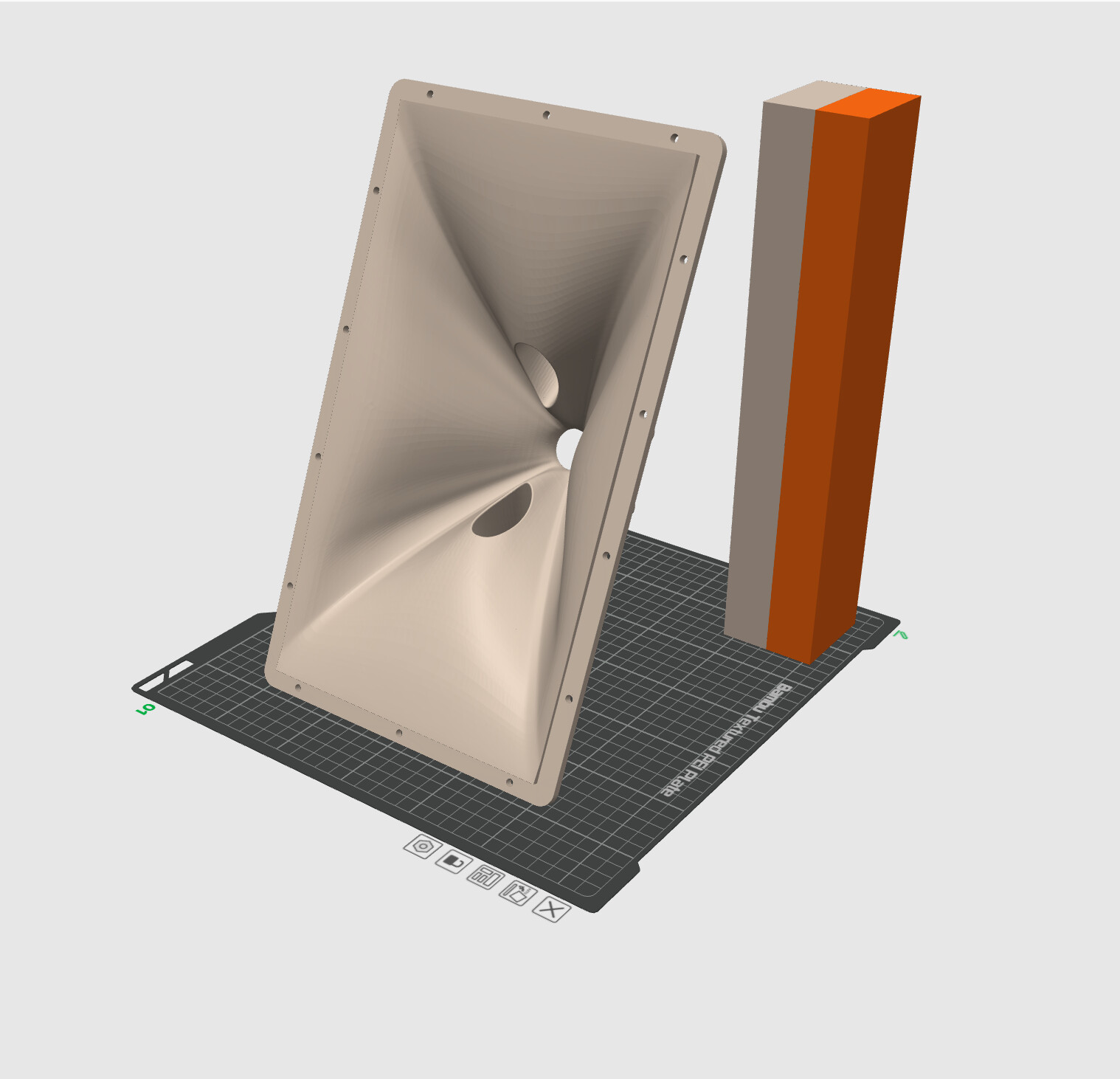
And then the fundamental question, why that tilt on the edge? Is it to fit the part into the printer? Would it be possible to tilt it to the right instead of to the left? That might completely make supports unnecessary.
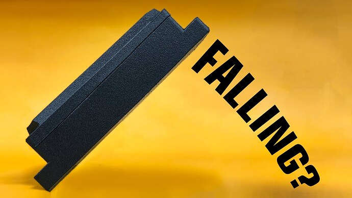
Of course it would fall over at some point. To avoid that, I would manually create some rib supports on the right side. Let me find that video again…
Maybe you can do something similar?
If there is good reason to tilt it the way you did, I would really think about PLA for support interfaces. It needs a bit of tweaking, so best experiment a bit on a small sample part. There is also a dedicated article in the BambuLab Wiki, using PLA as support for PETG and vice versa. Most importantly: set the flush volume from PLA back to PETG really high, otherwise, some residual PLA can completely destroy the layer adhesion of your PETG part, so that it breaks easily.
Really appreciate the help here. This pic might explain further…Loren42 is correct, its an acoustic horn so the inside needs to be the focus for smoothness.
I don’t know how much it transfers to sound quality but at least in optics small stuff much smaller than a wavelength is largely ignored by the light. It’s why you can use cheap diamond-turned mirrors in the IR that look like warm heck but that work great.
A 5kHz tone has a wavelength of 2.7 inches and 20kHz is 0.67”. I really don’t know how well it transfers but smoothness may not be required?
Oh wow, that is really cool!
With that background: Is rigidity of the material of any concern for acoustics? PLA is considerably stiffer than PETG. The main benefits I see in PETG are higher temperature resistance, far less creeping under load (e.g. a loaded spring will keep its shape, while PLA will deform with time), better resistance against many chemicals and more flexibility. PLA is stiffer and often can bear higher loads until breaking.
I’m not sure if any of the advantages of PETG are relevant for the horn? Maybe PLA would be the even better fit for the purpose?
I think if those surfaces are hidden inside the cabinet, I would accept a certain roughness and skip the interface material and use regular supports as you did before with the other adjustments I proposed that should already vastly improve the overhangs. You could sand the surfaces where the drivers are attached to get rid of the roughness from the tree supports.
one more idea:
Can you rotate the horn 90 degrees so that it lies on the long edge and place it diagonally on the plate? Then the functional surfaces would be (slightly tilted) side walls, that don’t need support at all.
You’ve got more scraping to do. There’s still support material still on the surface. Don’t cut youself with a woodchisel. This area is so large maybe a “card scraper” would work.
If you print again maybe tweak the Z gap settings a little.