I’ve been 3D designing for years and working with resin printing for the last 5 years. We recently got a X1 carbon and I’m thinking of getting a P2S for myself. So, time to dive into FDM printing.
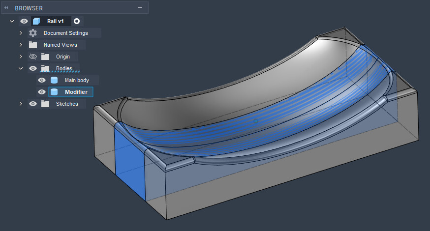
I’m trying to find a workflow to increase the infill density in certain parts of my model and found modifiers are the way to go here. Below is what I have so far, but when it comes to slicing there’s an issue.
In Fusion I have one component consisting of two bodies, the main body and the body to be used as modifier:
This also happens if I import one solid stl and use the modifier geometry within Bambu Studio.
So what is happening here and how do i get rid of those outer seams?
And is it possible to have ‘a part inside a part‘ to reinforce it?
Like this maybe:
In Studio or Fusion, make the modifier shorter by two line widths to fit entirely inside the walls of the main part? You can play with modifier size and wall layers, which can be set to zero if you wish.
I’ve been learning about similar/same issues recently as well. Not an expert, just what I learned so far…
For the surface issue, I’d keep the modifier part completely inside the main part, so it doesn’t touch the surface at all, with a decent clearance (ideally around the same as your top/bottom/side thickness or so).
As for the internal transition… the slicer indeed has trouble separating parts sometimes. Changing the wall count is a sure way, but can create the issue you found with too many walls. But changing the infill should also create a transition. Though w/out a wall it isn’t always pretty. So far I’ve worked around it by just using one wall on the inside part, vs. 2 or more on the outside, but don’t see a way to have it just use one or two walls at the transition point.
Does it help if you keep the modifier object as a “part” instead of making it a “modifier?” There shouldn’t be any practical difference if it’s not touching the surfaces.
Here’s a shot of a couple primitives I threw together in the slicer, the cube is the first/main object with a cylinder added as a part (not a modifier). The cylinder is completely enclosed in the cube. The only difference in slicing settings between the two is the infill density.
Oh, zero, I forgot about that, thanks! This puts in the parent/default wall count between the parts, from what I can tell.
–
Oh and I totally forgot maybe the most important point I learned…
The order of parts in the slicer’s Objects tree matters! They can be dragged around, and if the “wrong” order is used then modifications made to the higher level (I think) part may not have any effect.
Increasing infill percentage has limited effect on strength. In your case, I would build the strength into the model, by making structural supports, such as using the web feature of the Fusion. It is also simpler than making a custom modifier for use on Bambu Studio later.
@DWdesigns Yes for this model that would sure be an option but to test this workflow I added “internal webs“ as bodies in Fusion and set the infill to 100%:
Sorry if this was explained, I saw a little talk about it but not a full explanation. Although I did kind of brief through things too.
If the modified part is the same as the base part, it is like it doesn’t exist. It’s the same if you have two parts that are perfectly aligned, like for a multicolor print, but it’s all one color. The slicer will treat it as one object. Something has to be different within that object/modifier, to get the slicer to treat it differently. That’s why 2 shells had no shells, because since both sides had 2 shells, it just nullified it. When you bumped it up to 3 shells, then it put the wall in, 3 on the modifier side, and 2 walls on the unmodified side as per your default settings.
I’ve done this approach before and like it. Create little cavities within to force wall creation for added support.
This one is a little more straight forward. It’s a riser leg I wanted extra support on, so I diced up the geo some. The wall counts are just staggered to cause the split. I can’t remember what I last did an internal like web structure on, or if that was just experimenting. It’s been a minute.