There seems to be a loss of precision when a part is rotated in Bambu Studio. I have a logo on the surface of a model that appears to be parallel to the plate in Bambu Studio. It’s entire surface should be in one layer. However, the slicer shows that its surface ends up on two different layers, 0.2mm apart. The part has been exported from FreeCAD as .step file. In the CAD program the logo is on a surface rotated by 50 degrees around the x-axis. In Bambu it is rotated back 50 degrees to put it on the x-y plane. This leads to the problem. A better way is to rotate it 50 degrees in FreeCAD. Then the surface of the logo will actually be in one layer in the x-y plane, after the step file has been imported. I also had to convert it to a solid in FreeCAD because the rotation wouldn’t show up in the step file without this step.
It’s hard to visualize what you mean without a screengrab or perhaps even uploading a 3MF. This will allow the community to respond to you with a more precise answer.
Here is an example. The part can be rotated into this position in the CAD program or in Bambu Studio:
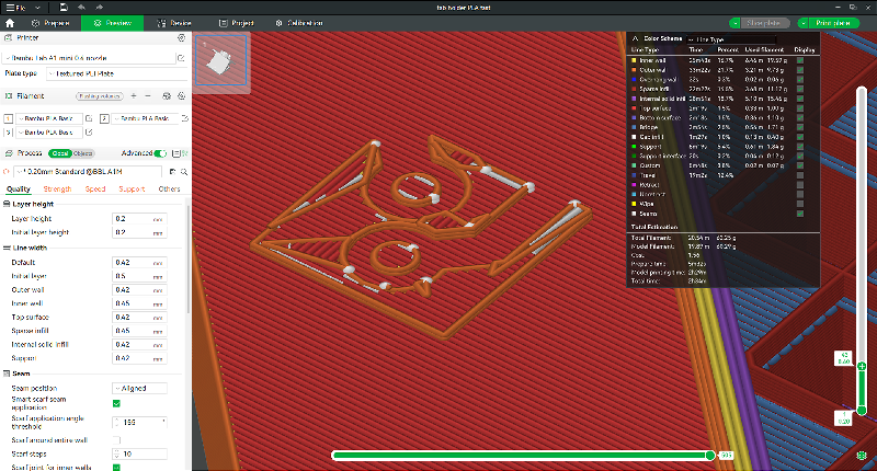
If the model is rotated in Bambu Studio, the logo’s surface is printed in two layers. First layer:
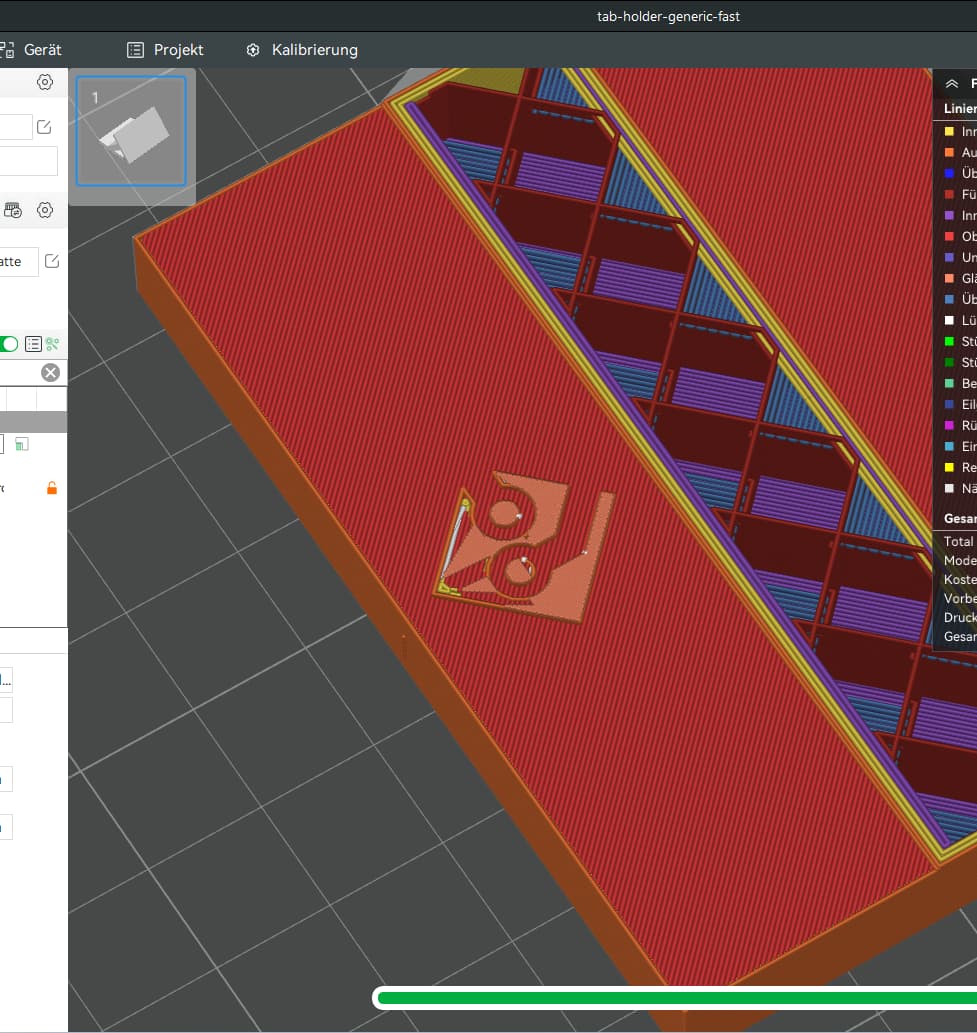
Second layer. Now the logo is completed but looks bad:
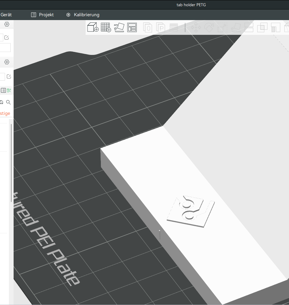
If the model is rotated in FreeCAD, its surface is printed in one layer:
Studio’s features aren’t CAD, they’re for people who don’t know CAD. Yeah, they’re not always perfect (try painting and see if you can figure out how it does polygon subdivision). But if you don’t have a better option, it’s better than nothing.
If you know CAD, don’t let Studio do anything except slice.
That’s an odd one. I’ve never seen any of my Freecad models do anything like that. Orientation never mattered when bringing in a STL or STEP file into Bambu Studio.
Did you add the sketch to the face and then pad the sketch from there? It’s almost like your logo isn’t fully solid for some odd reason.
Unless I missed it, did you actually try to print this? I aske because we’ve seen numerous occasions here recently where what was rendered in the slicer did not match the physical output.
The second question is: what do you mean by:
As @RocketSled stated, this is NOT CAD.
This whole thread makes me wonder what your expectations are. Can you expand with greater clarity the follow:
- What was the expected outcome(provide a visual example from FreeCAD)
- How did your expected outcome differ. Illustrations will go a long way avoiding the community to employ guesswork.
It’s up to you to help us help you. You have to meet us halfway and so far, your text and images are rather cryptic. I still do not understand what you mean by:
If I try to decode this statement from the original post, I have to conclude that you are assuming that there are layers in FreeCAD. That’s not how parametric CAD works, there’s only dimensions.
Here’s a suggestion. Go into FreeCAD and measure the distance that your logo is intended. Note that somewhere. So if FreeCAD says it’s supposed to be 0.2mm thick on the surface, then at least you have a reference point.
Now once you have that, go into Bambu Slicer and use the measurement tool to verify that the dimensions have transferred correctly. Here’s a simple example.

what do you mean by … part can be rotated into this position in the CAD program or in Bambu Studio
In order ot have a certain side of the design on the plate, I can rotate the design in FreeCAD or I can rotate it in BS. The end result should be the same.
What was the expected outcome
That is doesn’t matter if I rotate a part in FreeCAD or in BS.
did you actually try to print this?
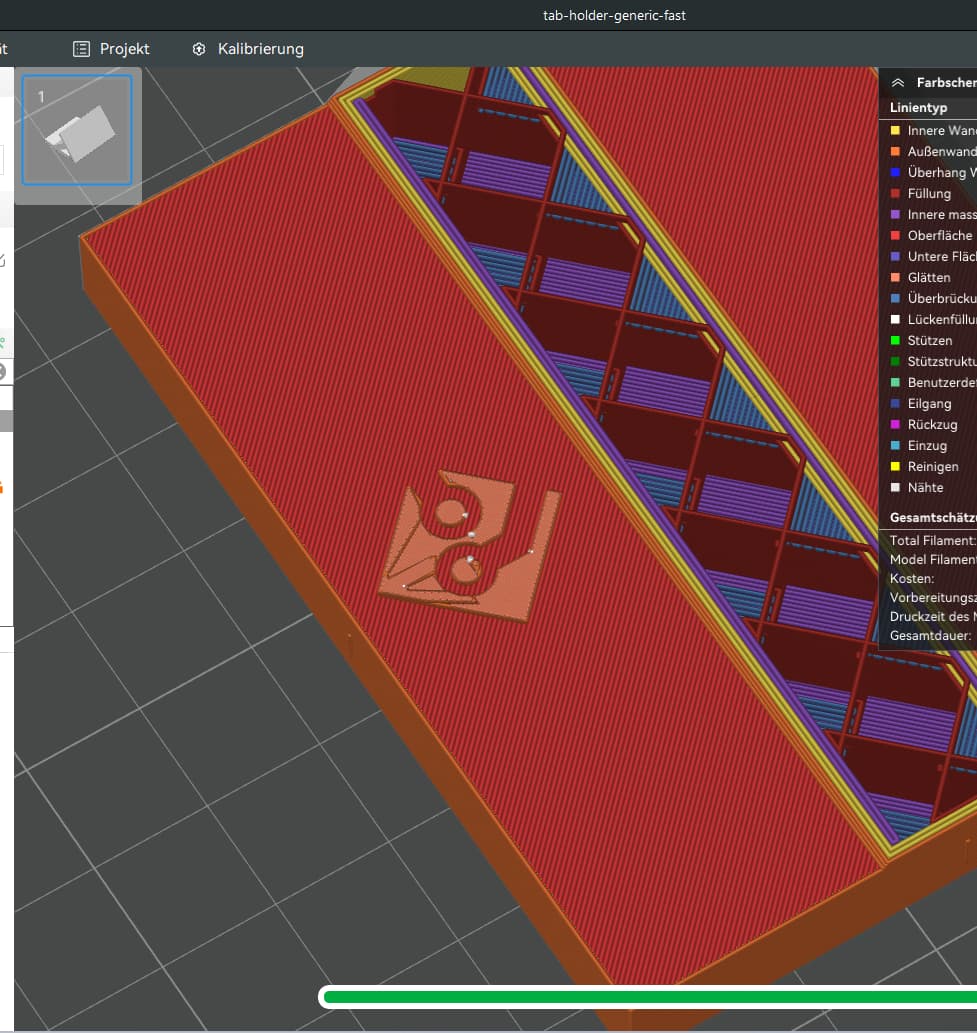
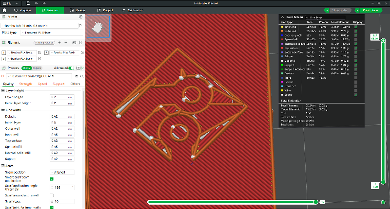
Sure. This print was rotated in BS and printed in PLA. One can see the defects in the logo (exactly as they apear in the slicer preview):
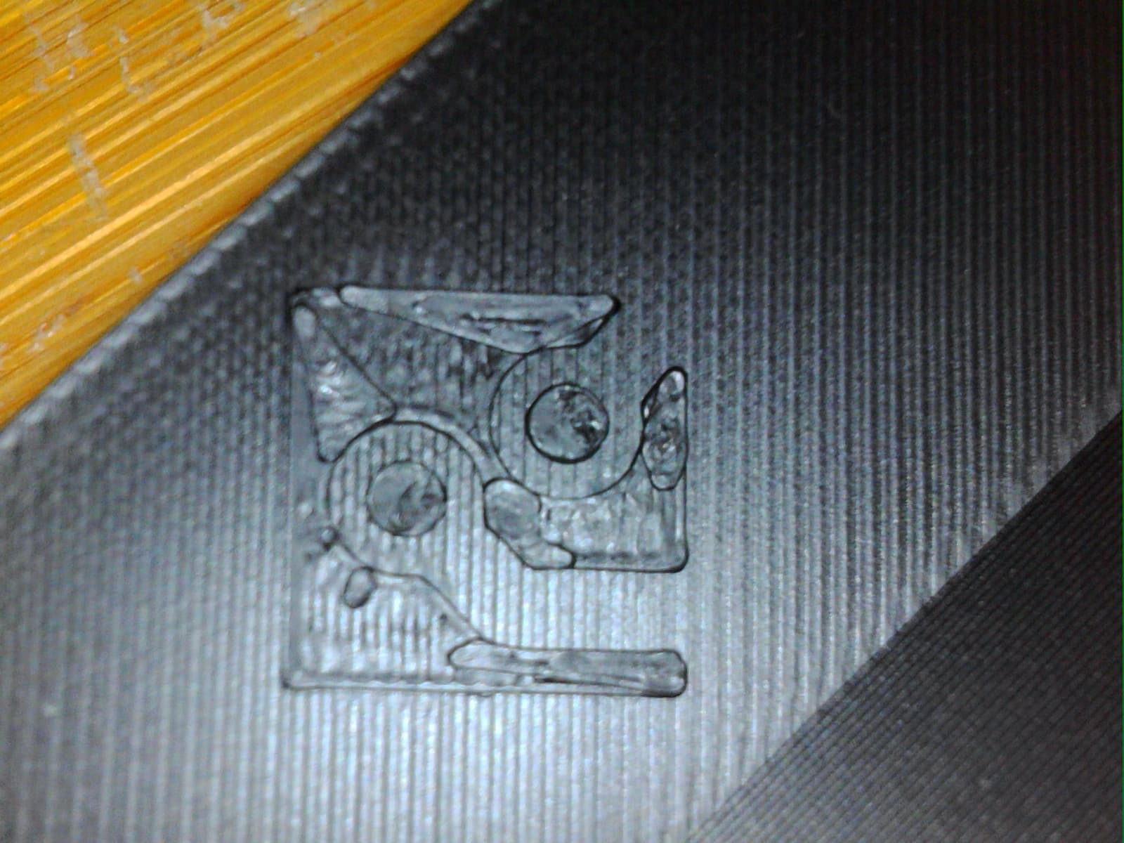
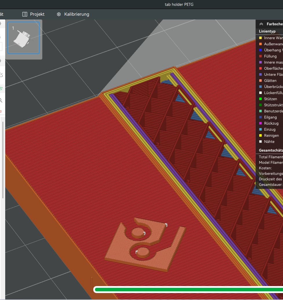
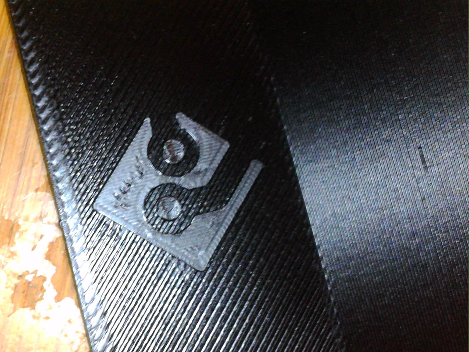
This print was rotated in FreeCAD. The defects do not show up (neither in the slicer nor the print). I only have a photo of a PETG print with badly configured ironing:
Go into FreeCAD and measure
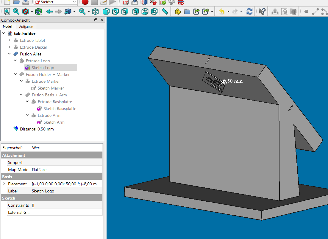
Everything is fine there. I’ve padded the logo’s sketch by 0.5mm, map mode is FlatFace.
go into Bambu Slicer and use the measurement tool to verify that the dimensions have transferred correctly.
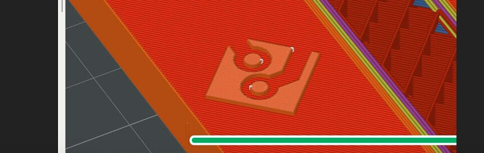
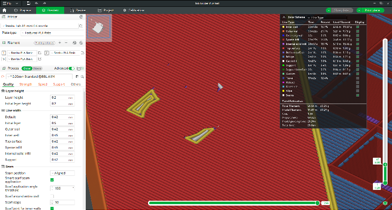
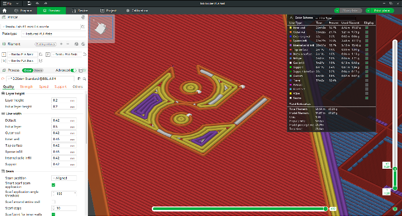
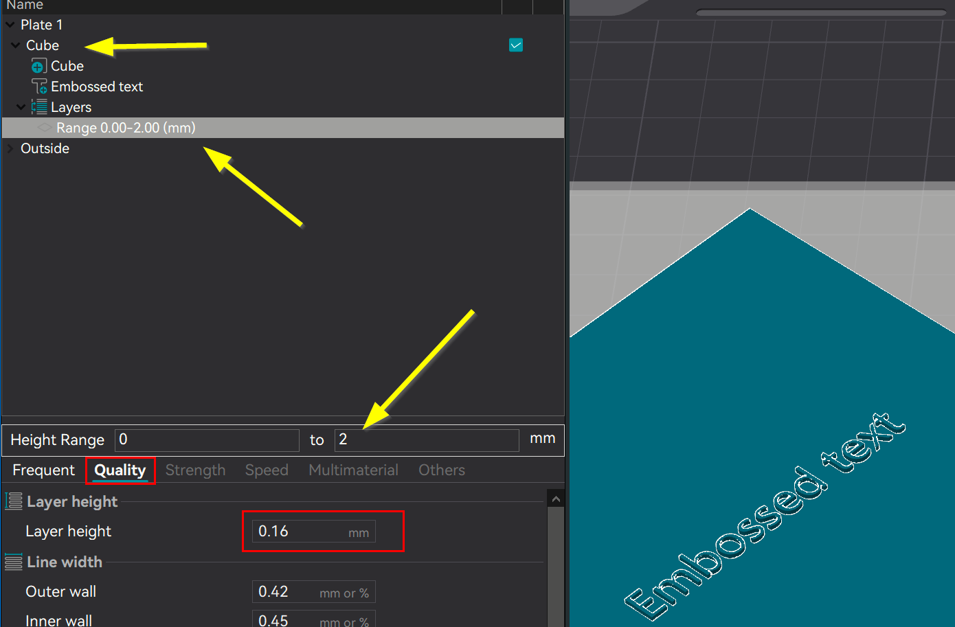
It’s fine in the Prepare view of BS, too. The weirdness is only in the slicer preview. Here are snapshots of the 4 layers that constitute the logo, in the order in which they are printed:

OK, thanks for that detail.
NOW we are getting to the heart of the issue since we are armed with the facts.
Your FreeCAD feature shows that it’s 0.5 mm in height. Thanks for confirming this.
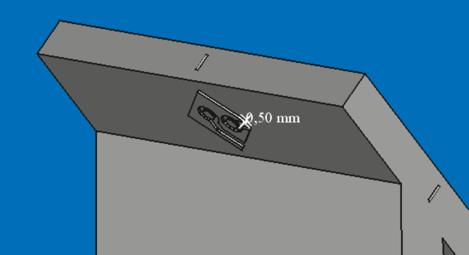
That’s important because the slicer is extrapolating into 0.08, 0.12, 0.16, 0.20, 0.24, and finally 0.28 mm layer heights, which don’t fit evenly within 0.50 mm. What you’re likely seeing is the algorithm struggling with trying to fit the STEP file mathematical constructs into uneven boundaries. Your image below is consistent with that sort of artifact.

To solve the layer issue, have you attempted to vary the layer heights? You, of course, realize that you aren’t forced to do this for the entire model but can use either the variable layer height tool or the Height Range Modifier.
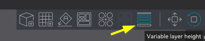
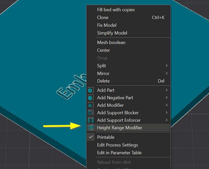
Both tools will achieve the same objective. Variable layer height is easier to use but Height Range is more precise as it allows you to dial in specific dimensional heights.
_______________________________________________________
I am still unclear on this original part of your post.
Do you mean around the Z axis? It’s important that we are clear on your meaning as it completely changes the answer.
you’re likely seeing is the algorithm struggling with trying to fit the STEP file mathematical constructs into uneven boundaries
I believe the artifacts in the slicer/print are caused by a rounding issue (that precision is lost in the step from FreeCAD’s internal coordinates to the .step file and that rotation exposes this). The logo looks fine in BS’s slicer if I don’t rotate the part in BS. The rotation in BS causes the artifacts to appear. I tried rotating the part by random angles around all axis. Lo and behold, the logo looks as expected. It gets steps when it’s not parallel to the plate, but no weird geometries pop up. It’s just the rotation that makes the logo parallel to the plate, which should be the easiest, that has weird artefacts.
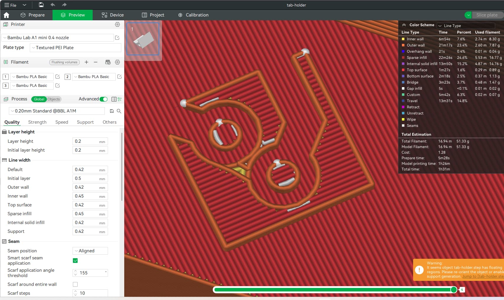
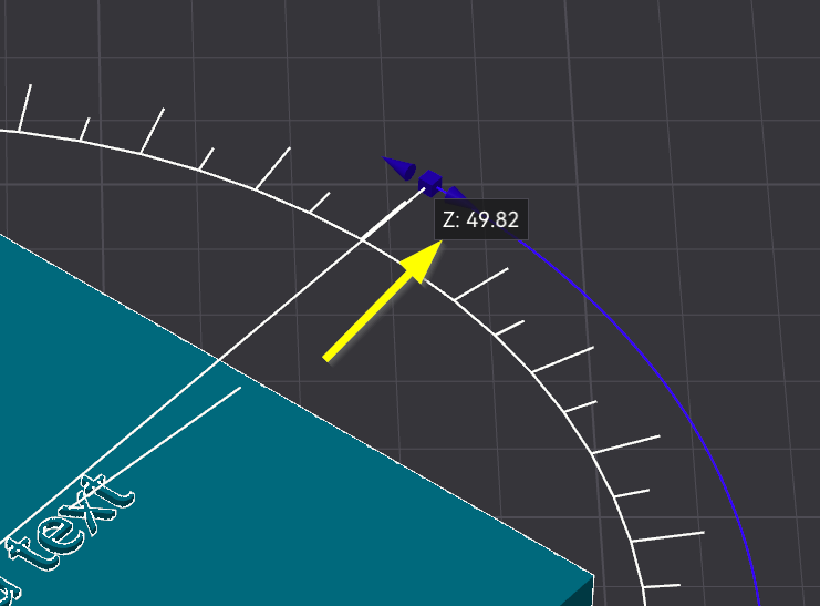
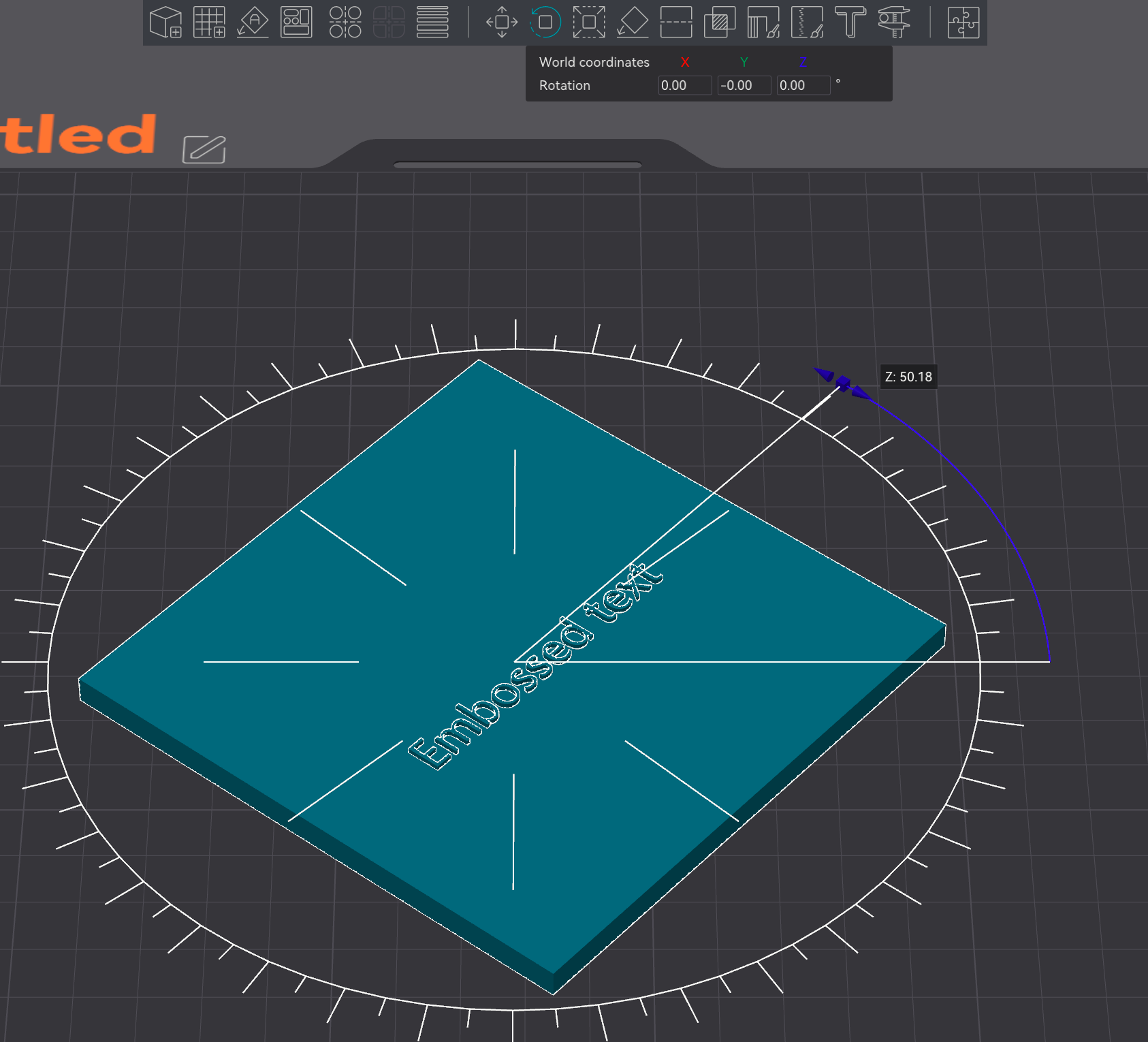
Part rotated in BS to make logo parallel to the plate (.e. rotated by 50 degrees), strange geometries appear:
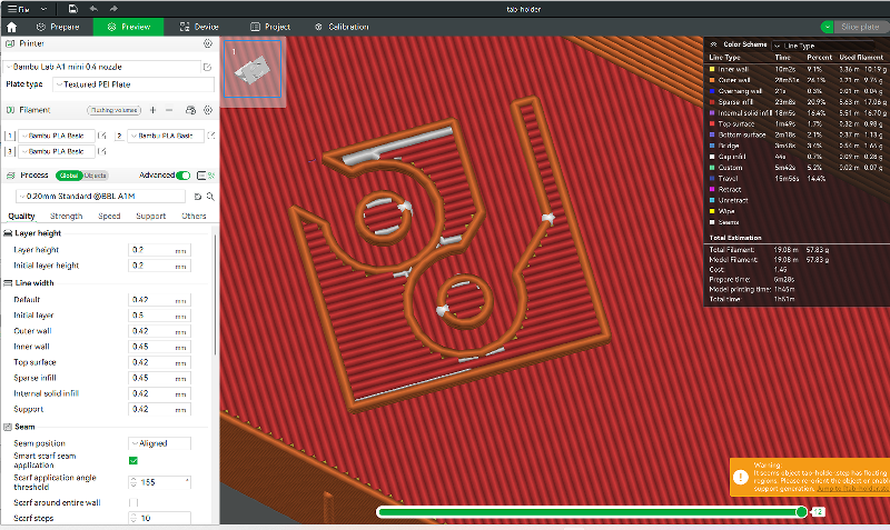
Part rotated in BS by another 5 degrees from the previous position (50 degrees - 5 degrees):
To cut a long story short, you may have to rotate in your CAD program to get the best result.
To solve the layer issue, have you attempted to vary the layer heights?
I never use that. I suspect it would cause visible layer lines.
That is a very logical conclusion. I’ve often encountered oddities like this when converting from CAD. Two tips I might suggest as potential workarounds:
First, try converting the STEP file into the AP203 version of STEP, if available, as it is the oldest and least feature-heavy version. The three STEP versions are AP242, AP214, and AP203, with AP203 being the oldest. Why do I suggest this? Newer versions often include features unsupported by older ones, which can confuse the slicer. I use ONShape, which lets me select the STEP version. I noticed FreeCAD 1.0 was released 4 weeks ago, but I couldn’t find an option for STEP version control. You may need a third tool to perform this file translation to an older STEP version if you want to enforce version control.
Second, remove the logo from the model entirely and split the model in CAD before exporting it as an assembly. This does two things: it isolates the geometry into two objects, allowing more granular manipulation inside the slicer, and it forces the slicer’s algorithm to evaluate the components separately. Both approaches can provide greater control during slicing.
I wonder if using the adjustable STEP-to-mesh import parameters of Studio 1.10 could correct the problem?
I wonder if using the adjustable STEP-to-mesh import parameters of Studio 1.10 could correct the problem?
YES! I cranked it up to the max (linear deflection 0.001, angle deflection 0.01) and now it looks good. There is still a tiny error in the logo vs roation in FreeCAD but it’s much better.