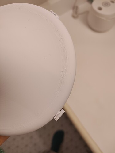
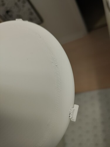
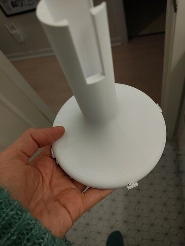
Hello everyone, so I’ve been printing for a while on other printers and got a XC1 a year ago. I’m always printing the same files (designed by myself) that I sell. I’ve been having this issue with my XC1 where I can see those rough lines on the print (see pictures). It’s like a ring of roughness all around it.
It doesn’t do it on my other printers. It’s always the same files, printed in PLA. I already tried a few things :
*adaptive layers was the first thing I did. Lowered the layer height to 0.8 in that area, smoothed it out and it didn’t work.
*changing filament brand. -slowing down outer walls speed
*turning off auxiliary fan
I was wondering what else I could try to to make it look smoother. Sanding down is not an option especially on the black color, it makes it look worse.
Thank you for your help
Assuming it is not an extrusion or calibration related issue…
It is a quite shallow angle…
Do a small test print of a slope with a similar angle and check the nozzle during the print.
Quite often it is residue build up that ends on the print during these unfavourable angles in round objects.
If that is the cases than take the sock off, clean it and use silicone oil on the outside where the nozzle is.
Use a cotton bud or lint free cloth to also wipe some silicone oil over the nozzle - wipe off with a dry paper towel then do some thin prints so the top layers can remove all leftover silicone.
After that not much of residue should accumulate during printing.
I’ll try the silicon clean up and will update! Thank you.
Unfortunately it didn’t work…I’m not too sure what else to try.
Hi, it seems to me that you have a very similar problem as me. I came across something similar after a firmware update. I managed to solve this problem by disabling deceleration on overhangs. If that doesn’t help you, maybe you can find a solution by printing with dynamic layers.
It may not address the root cause but you can influence that in the slicer by modifying your flow rate for top surface - Your “rough edge” is overextrusion of top, being squeezed out as the nozzle intersects and turns around at the wall/perimeter boundary. So of many possible approaches, you can go directly to just less flow in that surface to remedy it. If you’re using orcaslicer, you can also attempt to use Small Area Flow Compensation. (your slice preview → flow rate visualizer will be able to show if you benefit from this)
I’d strongly encourage doing a flow RATE calibration test print, as well.
I had to print some templates for accurate holes and cuts in some steel cylinders.
Since it is all as thin walled as possible I decided to add an upside down saucer thingy to increase the layer times.
Could not observe any of these blobs or rough walls.
Then I remembered this pesky roll of PETG that never wanted to print properly…
The PETG was changing diameter over a distance of over one metre.
Like a slow tidal wave going from near perfect down to around 1.68mm and rising slowly to normal.
With that I often had artefacts like in the above pics…
But also areas where under-extrusion was a problem.
I strongly suggest a proper filament calibration, especially for the flow ratio.
Since there can be some confusion >
Don’t be shy and use a good magnifying glass and proper light so you see the top layer lines of the calibration patches from all angles - leave them on the plate for this check 
The key for the first round is NOT to go with the best looking patch…
0 is the patch with the default flow ratio, the negative ones go down in flow, the positive numbers go up.
The second round however only goes DOWN 
Means that for the first round you need to know what to look for so the second calibration round can give you an improvement!
Start on the negative end of the patch scale - see these gaps between the lines?
Move up on the scale until you see them disappear, now take the magnifying glass.
Check THAT patch carefully - it should have no gaps between the lines, nowhere on the entire patch.
If not move up one number and check again.
Pick the patch number where the gaps are gone or if slightly inconclusive the number above.
Do not pick a number where just most of the centre looks great as this will certainly give you a 0 for round two.
The second round should always produce a patch other than 0 that is the best with those before and after being worse.


