If it only applies compensation via the y-axis then the print will be orthogonal, but the width along the x-axis will be short. It needs to move further along the x-axis to be the correct width because that axis is skewed.
I agree that’s correct. That’s one of the “limitations” I was referencing.
Rather than contemplating how the skew comp could be improved - I was trying to investigate and break down how it’s actually functioning. To me, its intended purpose just looks to be “straightening” the axis, not correcting the geometric shape. So yes, the width of our prints are going to be undersize in X relative to their Y measurements, as a physical phenomena of the X-Axis/Gantry being crooked (the programmed X move is physically happening at an angle, which means it won’t be the correct length when measured from the parts actual axes/orientation).
You could go allot of different directions about what should be, but that looks like what is happening. To me the real answer here is investigating and focusing on improving the physical squareness of that gantry, My sense is that it will have other implications on print quality - and that the compensation, while it has its place and is useful within a range, is ultimately just a bandaid.
I’m glad this info came out, I hope to see more information and more codes for scaling and skew in other Planes/Axes released from Bambu
@Thermal_Runaway This is great! Thanks for all the work you’ve done on X1plus and now on skew calibration.
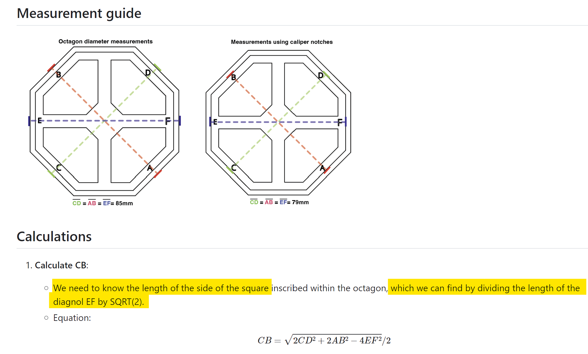
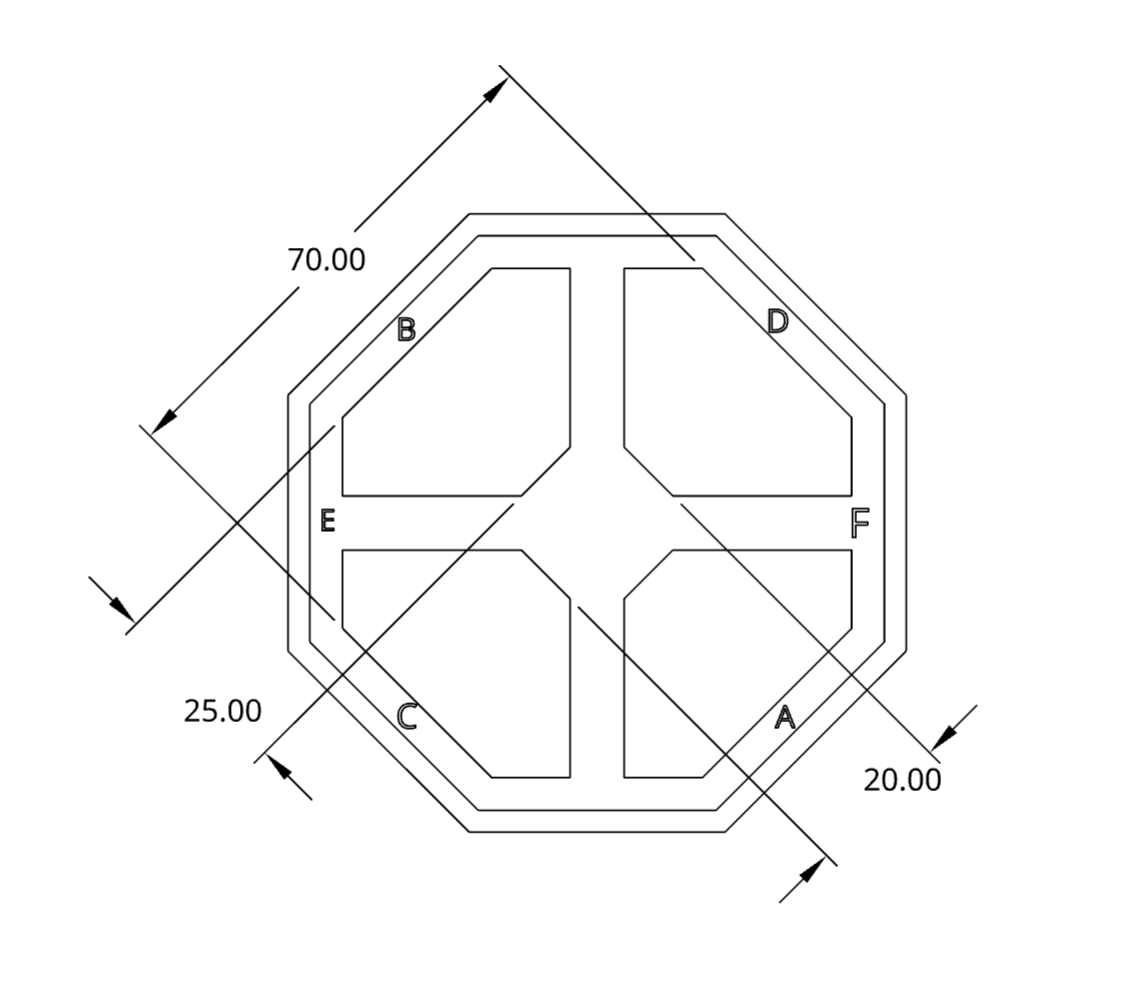
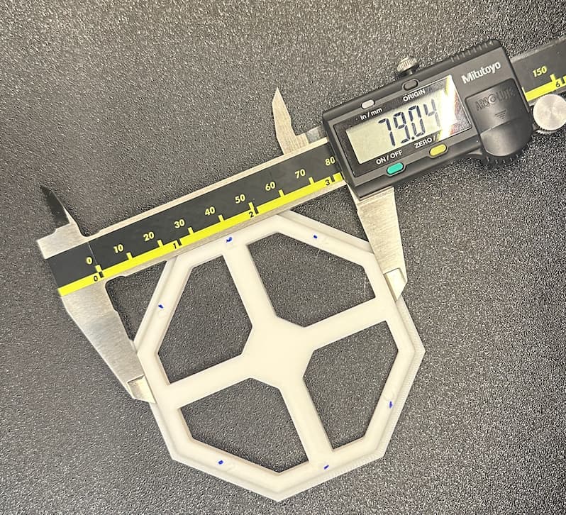
The skew calibration model I have made allows you to make the same 3 measurements from different sides of an octagon
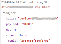
To verify that your skew factor has actually been applied, you can publish the M1005 command with no arguments and the printer will output a response via MQTT
I have a legitimate question about this statement above. How can using the octagon for measurement be “far superior” when the end result is that you’re using it to calculate the side of the square that we have been physically measuring.
Maybe it’s more convenient or nicer to try and measure a round number (which the octagon gives you), but I’d challenge that the most accurate way is to measure the “squares” dimension directly rather than calculate a proxy for it. It may be a minor point, but seems like it does potentially add an error of its own.
“Far superior” may have been a bit too strongly worded because I have not proven that it’s more effective. I just find it easier to take 3 similar measurements.
I would like to point out that the calculation shared on here for skew factor in radians also uses a trigonometric relation to calculate the length of a segment not being measured Skew compensation in the Bambu X1C Firmware - #15 by klomar
Applying trigonometry to a measurement doesn’t necessarily add error to that measurement
I have compared the square model with the octagon on my printer and I am not able to measure a difference in the accuracy and precision. i’d like to see more data points though. I’ve had a few x1plus users test it, and I think the “far superior” aspect is the automation of the whole process
Skew compensation is being applied. My prints are corrected for skew.
I subscribed to the X1C MQTT broker, topic: "device/<my serial number>/#".
I published a payload: “M1005”, topic: “device/<my serial number>”.
The response was "M1005".
What would a typical response be if the skew value is saved?
When you say “has a skew value saved” do you mean saved to RAM or through a power cycle?
After reading Marlin and Klipper’s info about skewness corrections, the purpose seems clear, as @jason.t stated:
I still have many open questions, but most will require further details regarding the model assumptions.
@klomar you are rightt.
I wasn’t aware of the [In] methodology. I will give it a try when possible.
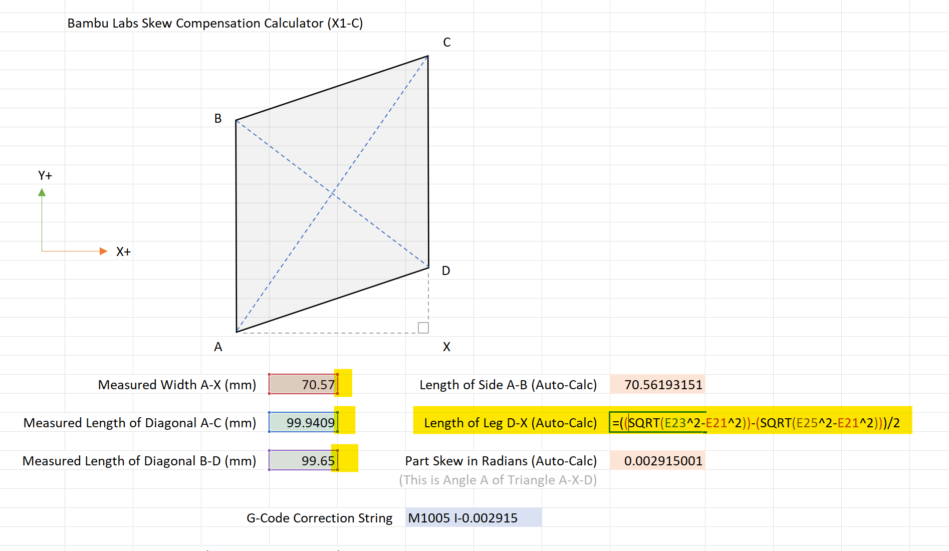
Both of you are likely to be correct, but I cannot understand the difference. Cant the skew angle be assessed by only the AC and BD measurements, i.e.:
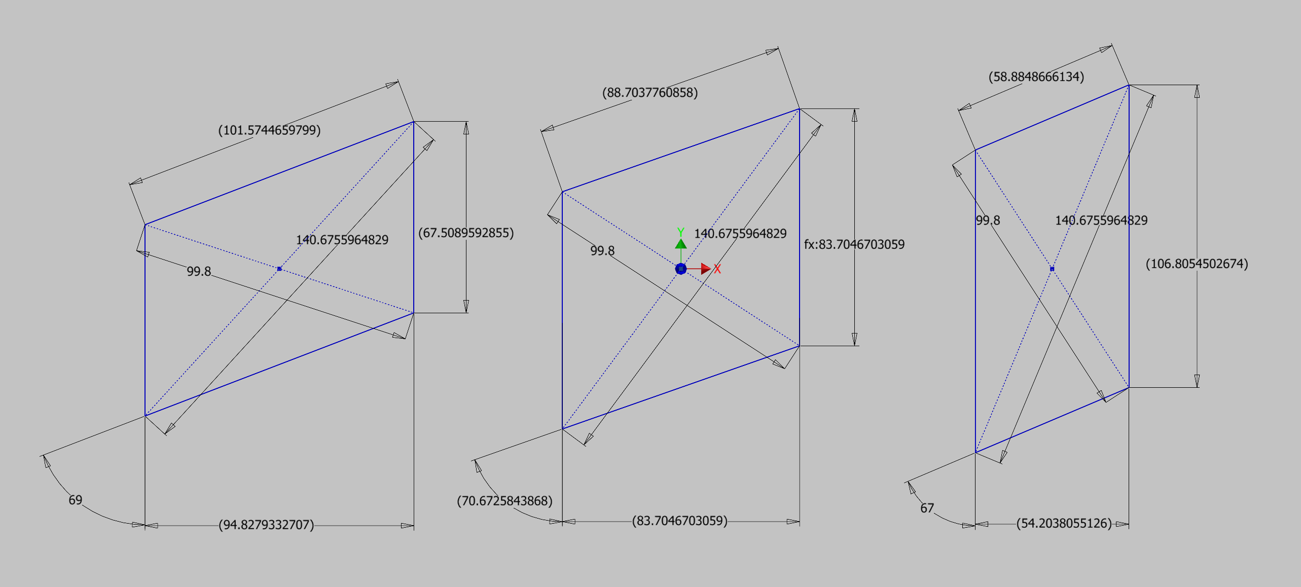
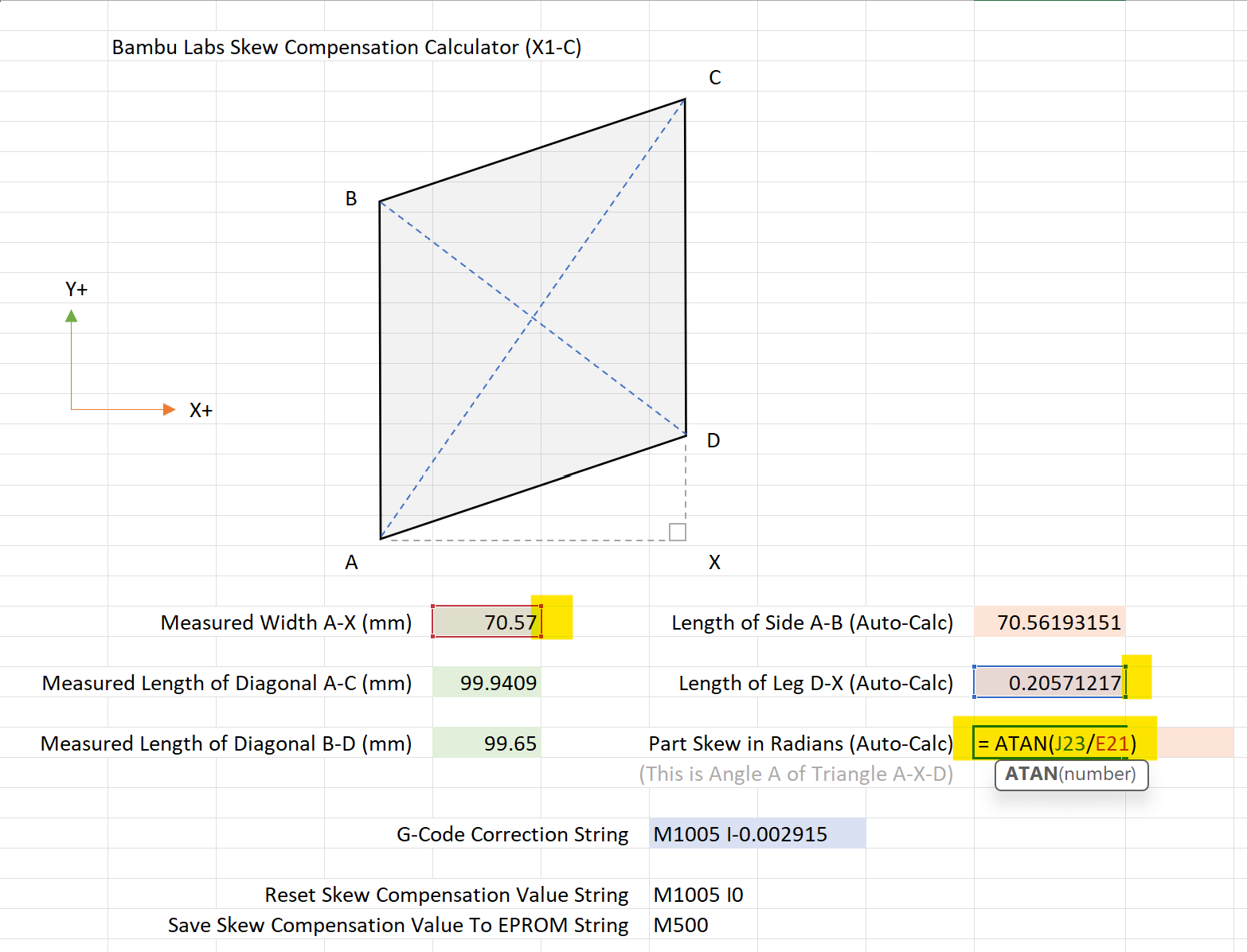
These three examples below all have the exact same diagonals but are all different angles. You need a third piece of information to solve the angle. M1005 X Y method has to be using a static value internally (that’s representative of the nominal size of Bambu support provided model) for its calculation that might not match the physically printed piece that you measure - so you get an angle/correction that’s probably close, its an improvement in the right direction, but not exact (it will be over/under depending on if your test print was small/big).
M1005 I sidesteps the variance by letting you calculate an exact value yourself. The rub here is that we haven’t totally unified on how that should work (model to use and math). To me, through discussion here, its become clear that the most accurate way is measuring the diagonals and the width of the “square” you printed and solving for the angle of skew with that information like has been mentioned above. (pretty much @klomar 's original info with some additional clarifications)
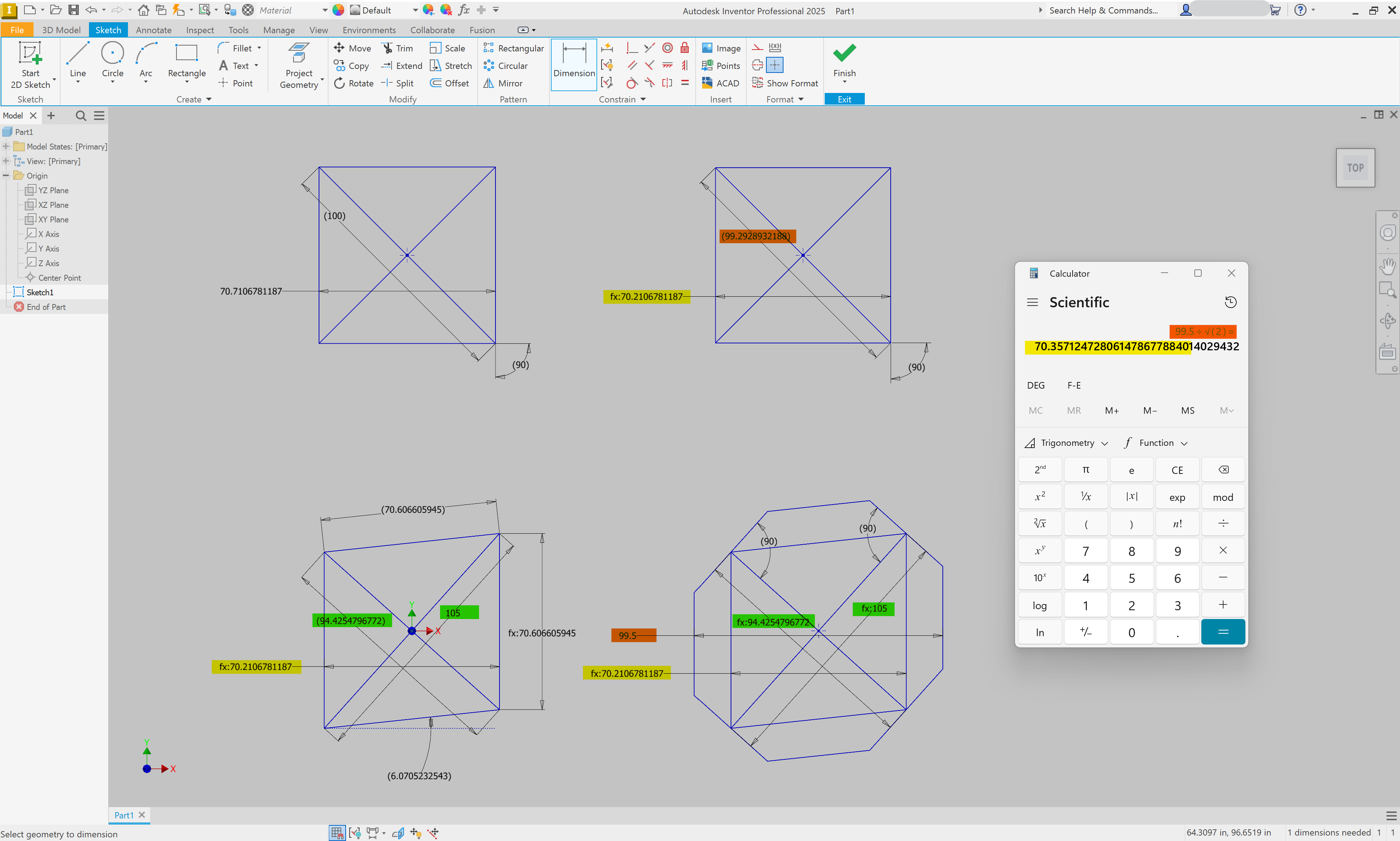
I don’t believe that the necessity to do trig adds error, but I think your calculation with the octagon only works when everything is nominal. Take a look at this below and tell me if you think I’m looking at it wrong…
The square represented here in the upper left has a nominal diagonal of 100, if I print it and it actually measures undersize by .5 on its width then it looks like the square in the upper right.
Now, physically the print is skewed - so it really looks like the “square” in the bottom left. Next to that I place an octagon, skewed by the same amount (evident by the inscribed square) that’s also measuring .5 small on its 100mm width (measures 99.5).
Doing this and then running the calculation with the octagon doesn’t yield the same result as the physically measured “square” thats inscribed inside of it.
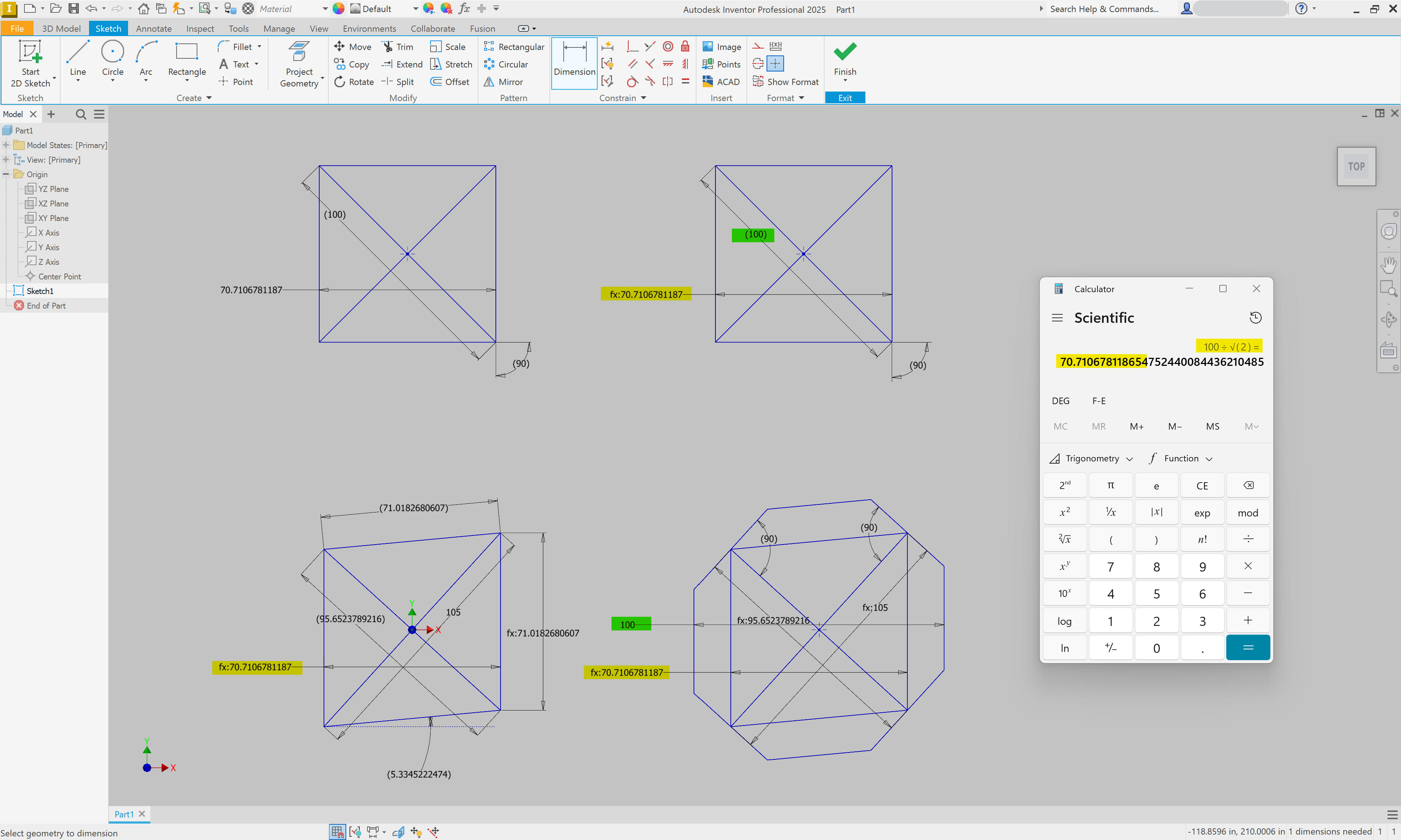
Here’s the same sketch, with all the same shapes, but updated to be their nominal size - and here the math works out. It’s not that the math is wrong, it’s just ignoring that there’s extra variable with the physical part size (and/or the way the skew physically manifests)
I may be wrong here and I’m happy to be corrected if that’s the case, but I believe there’s an actual difference between the two methods in the physical world (measuring the square vs. measuring an octagon)
I don’t know the answer to your question, because both of our logic seems valid. Also you clearly discovered that M1005 I much better than M1005 X Y, so I know you’ve spent as much time as I have thinking about this.
I’m going to take a closer look at your images later because I’m on mobile right now. The relations ive used to derive the length of the side of a square circumscribed in an octagon from the diameter of the octagon is mainly geometric relations rather than trig. I can write it out later and you will see why I’m so adamant that this calculation doesn’t introduce error.
The other thing about this is there are 4 sets of measurements you can take inside the octagon that should be whole numbers, so you can test dimensional accuracy and calculate your skew factor all at once. I don’t have a great diagram of this handy, but here is what I’m referring to.
I realized after writing my last message that you don’t need the explanation of the relation itself, because that’s not what you’re asking about. You’re concerned that this skew calculation method is more susceptible to error because the 3rd measurement relies on several geometric constraints being true, such as
all sides of an octagon are equal
all internal angles of an octagon are equal
And of course these are not all true in reality, so the relation starts to fall apart. Is this your point?
I would argue that the accuracy is most subject to human error rather than error in these calculations, so having more reproducible measurements means less time spent repeating this calibration. Would either method really result in what we’d consider correction after just one calibration step when skew is abnormally high? I see flaws in both methods that result in them requiring iteration, but with the octagon you can actually measure diagonal and orthogonal skewing. Maybe this will be more important when Bambu implements skew correction along multiple axes.
Maybe we should apply large skew factors to our devices, print each model, and compare findings? I don’t know what the largest skew factor that can be applied is, but I want to see a very exaggerated example of this
When the gcode command returns nothing, this means there is no value saved to EEPROM. To save a skew factor, you publish the command followed by M500. Then you should start receiving a response when you publish M1005 again. The printer refers to it as “XY_comp_ang”. I have this process automated in my python script, but I am fishing skew factors directly out of syslog instead of mqtt so the code might not be helpful
The way you are doing it by putting it in your print startup is perfectly fine too. The advantage with saving the value to EEPROM is you can set it and then forget it. As I’m sure you’re aware, there is a bug preventing the skew factor from being saved to EEPROM correctly, but I’m assuming Bambu will eventually fix this.
Also, I am looking into this so I can make as simple of a feature as possible in X1Plus so I may be on some unhelpful tangents. Anyone interested in this for other devices and knows how to tweak HA workflows, just let me know. I have a script running on x1plus that preserves my skew factor between reboots, and I can explain how to set this up in an HA workflow.
What I’d like a comparison of is how many iterations it takes to correct skew to a satisfactory level with the square model and with the octagon. I am suggesting we can apply large skews, print both with said skews, and back calculate these relations to see if one contains any greater error than the other. My hunch is that the results will be very similar
I’m not sure if this results in a response being published, but I did verify that after saving, if you then publish M1005 alone you will get a response here:
device/#/report/mc_print
edit: re the script for X1Plus - It’s up on github but I have no instructions on how to set it up yet. I’ll let you know when I have instructions ready soon. It also will start logging XY_comp_ang values to /tmp/x1plus_data.log along with some other useful data
I’ll have to catch up on the rest of this thread later, but one last point to clarify:
Difficulty in obtaining consistent measurements is not an issue that plagues the users posting in a thread with 145 posts about how to most effectively measure something, I think we can probably all agree. But the many users who will never see this thread don’t all have experience using calipers.
An octagonal design allows you to take advantage of an inset that caliper jaws can lock onto in perfect alignment. This should reduce some user error in measurement. allegedly.
Reset skew compensation with M1005 I0 at the start of your Machine end G-code if you try this or it might cause print head collisions while the end gcode or the next start gcode is running. Extreme skew factors may cause collisions when the print is running.