So, I have been reading, watching a ton of youtube videos, but I really can’t find any help regarding my issue. It’s probably due to me not fully understanding the 3d printing language yet - so excuse me if my issue is totally n00b!
I have 35 years of 3d modelling experience, so I should know my way around the modelling part - I have tried all kinds of combinations in Lightwave and Bambu Studio, boolean substract, union, add etc. - but no luck to print those solid insides to get a stronger connection between the plate and the “hinges”. They always end up only being printet on the top surface.
I really hope this is just a n00b error from my side
I have tried to add modifiers, wall thickness, split to parts, objects etc. no luck.
It seems Bambu Studio keeps optimizing the inside part away or makes an error with two objects colliding.
It is a slicing problem, not really much of a design problem.
The issue is that the slicer interprets everything by layer, so whatever is one layer will be printed as such.
The amount of walls on the outside and the rest is infill.
I did not have to fiddle like this with Studio but in the past I solved issues like that in a quite simple matter >
Have both parts, bottom and hinge and set them as an assembly of individual parts.
If you change the slicing setting by object the slicer should work it out as planned.
Another option I sometimes use it to include an additional void.
E.g.: Where the hinges meet the bottom I would ‘insert’ a hollow slot.
Like this the slicer has to create the walls for that slot and if the match the walls of the hinge it gives a lot of additional strength.
So they are modeled as separate parts? I would merge the plate and the hinges together in your modeling software and then when you import into the slicer, create a modifier that overlaps both the hinges and the plate area. Change the infill density of the modifier to increase the density. Here’s a part where I’ve done something similar. The pegboard hooks were exported out of Fusion 360 along with the spool holder as a single object and then I added a modifier in the slicer to increase the density where the pegs connect with the backing plate.
You have it set to 100% infill right? You might get better luck with that sort of interface at non-100% infill, and if you want those struts to continue being represented in the infill portion of the print, model them as modifiers at 100% infill.
Also, if you want those pieces to be stronger, the stark 90 degree corners orthagonal to Z are a big stress point. consider roundness, chamfers, etc.
I have tried as seperate parts, seperate objects, merge into one object using various boolean/welding/modeling techniques in doing so. Same result.
I did try your modifier proposal - I saw in a youtube video - but it really does not work out so something else needs to be fixed. I seems the modifier is just filling up the area but the hinge part is still on top - if this makes sense?
But I will try again experimenting with this method. Thank you for your input
Nope - infill it not 100%. As long as the hinge part is not even visible in the object after slicing, I don’t think 100% infill is the right solution. I want to make sure the object is actually printed the way it’s modelled. This way I can control the strength of my design directly in the modelling.
I would really like if I could have the slicer do very little optimizing and just be true to the model design.
Thanks for taking your time to get back to me
Hopefully we can get you back on track. And hopefully this explanation will help clear things up.
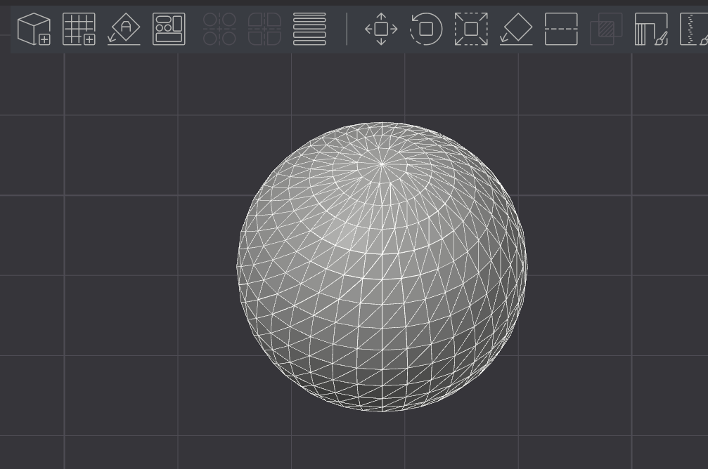
To help troubleshoot, it might be useful to take a quick step back and look at how these tools handle geometry. Software like Lightwave, slicers, and Blender all work with mesh-based models. That means the objects aren’t solid shapes in the traditional sense - but rather surfaces made up of interconnected triangles that form a closed shell.
If you’ve ever seen an “Open Manifold” error, that usually means the mesh has gaps or holes - so the slicer can’t interpret it as a proper solid. Slicers need fully enclosed geometry to work correctly. And just as a heads-up, every model brought into Bambu Studio gets converted into a mesh behind the scenes - regardless of the file type you start with.
Here’s a quick look at a sphere with mesh view enabled in wireframe mode:
So if you can keep in mind that all models are converted into a mesh, then it may help to understand that what’s happening to your model is that upon import, or Boolean union, you’re left with a solid single envelope.
The trick is to get the slicer to believe there are two objects, which prompts it to recognize an internal structure it must follow.
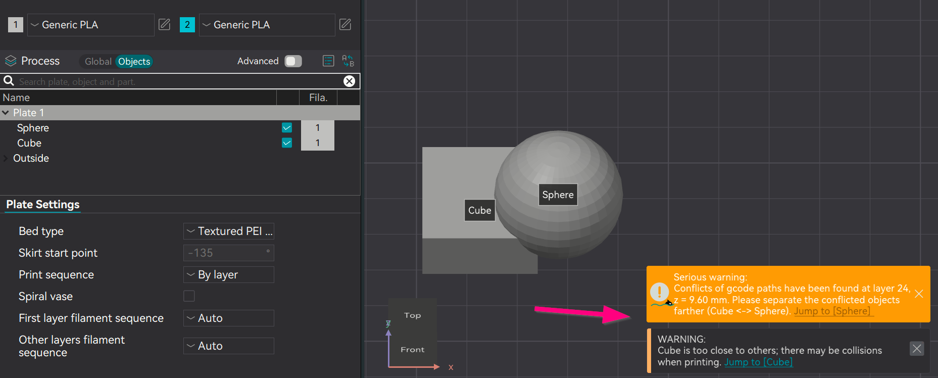
First example - Clumsy, and the slicer often won’t obey (click gallery to zoom)
In this example, we’re just taking two objects and overlaying them. Note that there is a conflict warning. For the life of me, I’ve never been able to explain why or under what conditions, but the slicer will randomly refuse to allow the conflict to go to print (grayed out), while other times it proceeds. If anyone has an explanation, please post it.
Disadvantages:
As independent models, it can confuse the slicer and prevent printing, as it thinks the nozzle may collide with the objects.
Arranging items precisely is very hard, and auto-arrange will break any alignment.
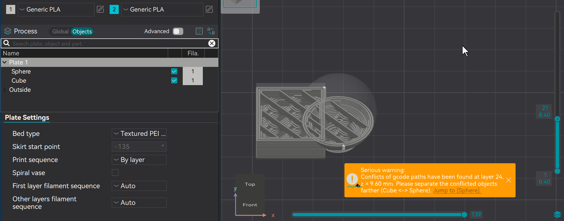
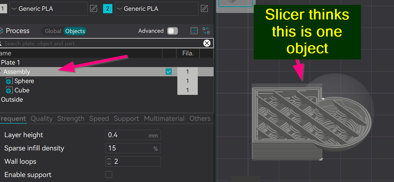
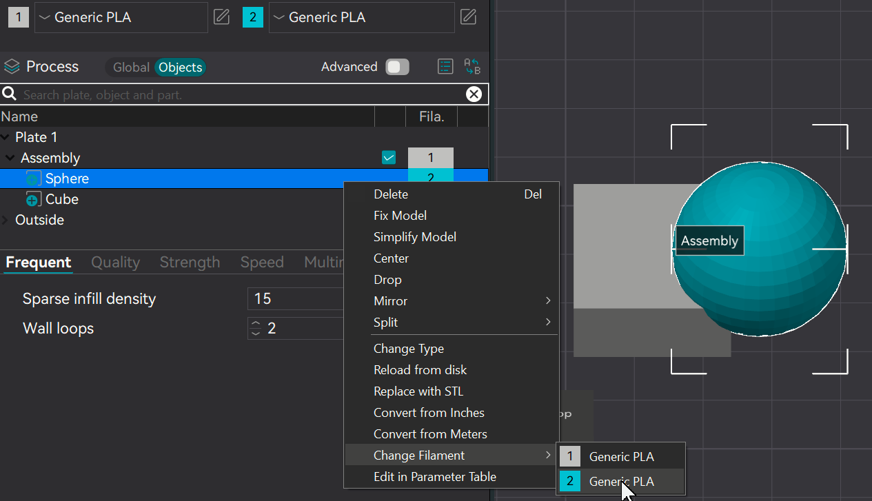
Second example - Fake the slicer into believing there’s another filament
If we use the Boolean or Assembly features, we avoid the auto-arrange and alignment problems, but as you’ve seen, we now create an internal geometry problem.
However, if I add a second filament of the same type into the session, the slicer mistakenly thinks it’s another color. For non-AMS users, this is easy. For AMS users, the challenge is that the slicer will want to use the second spool. Since I don’t own an AMS, I can’t advise on any workarounds, but with a single-spool feed, the slicer will just use one filament even though it sees two in the model.
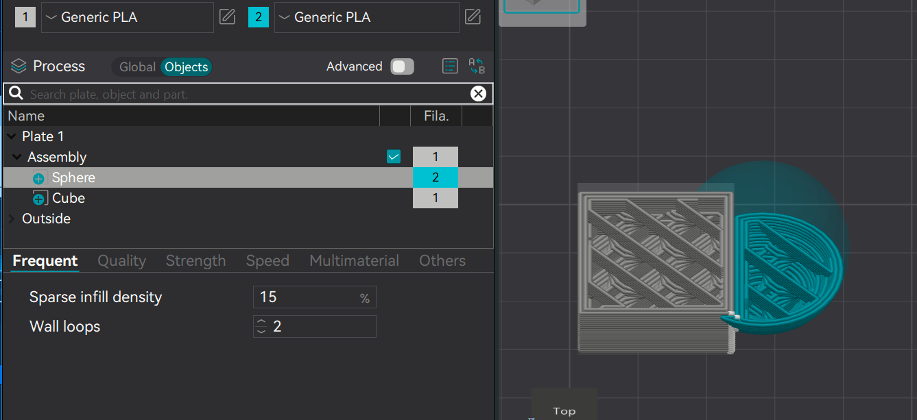
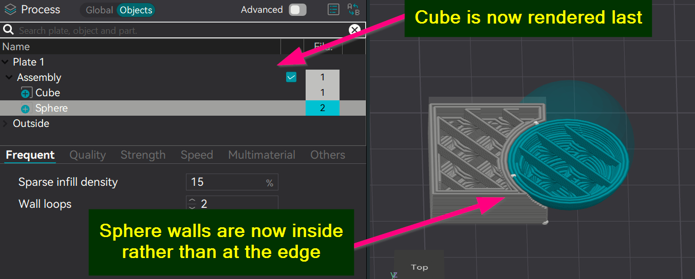
Here’s a trick: if you click and drag the order of the objects inside the assembly, you can get the slicer to render in a different order. This is clumsy and requires trial and error, but it can be made to work. In this example, I’ve embedded the curves of the sphere inside the cube, which gives it greater strength.
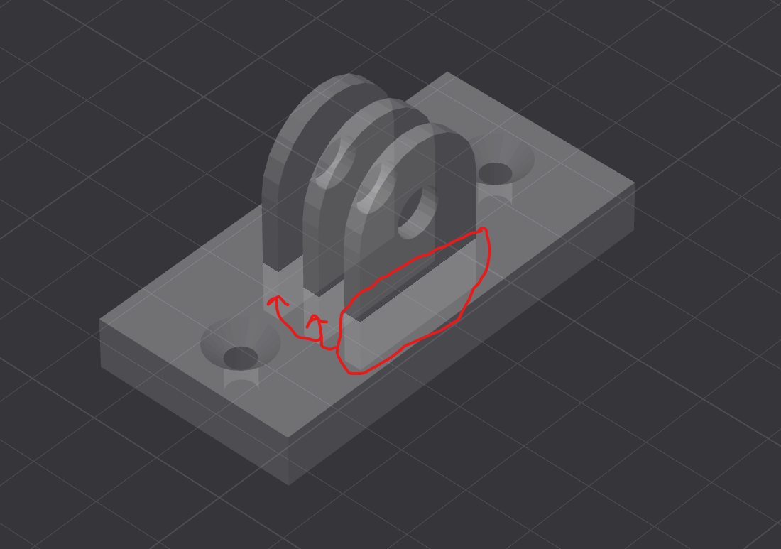
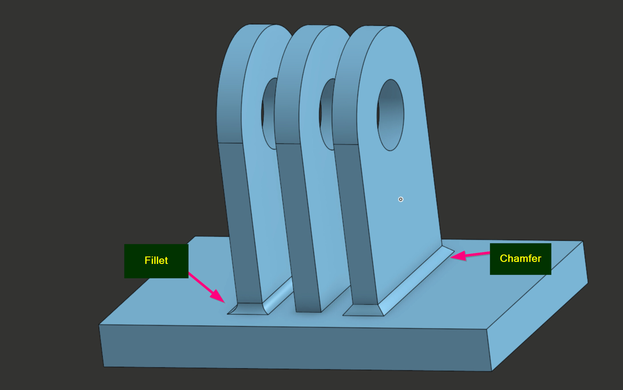
I can see from your example that you’re making some kind of bracket. I can also see that this design lacks strength in key areas. You have a sharp edge along the filament boundary which will snap off under stress. The solution is to use a fillet or chamfer to relieve stress along these lines. Here’s what that might look like. While both do the same function - spread out stress across joints - Chamfers are stronger while Fillets look prettier. Chamfers also print better. So if you’re looking for strong functionality, chamfers will likely perform better. Increase the size of the chamfer also spreads out more stress. It is a trade off between fit and strength. It is possible to make the chamfer too large so that he pivoting part starts to scrape against the chamfer.
[Click to zoom]
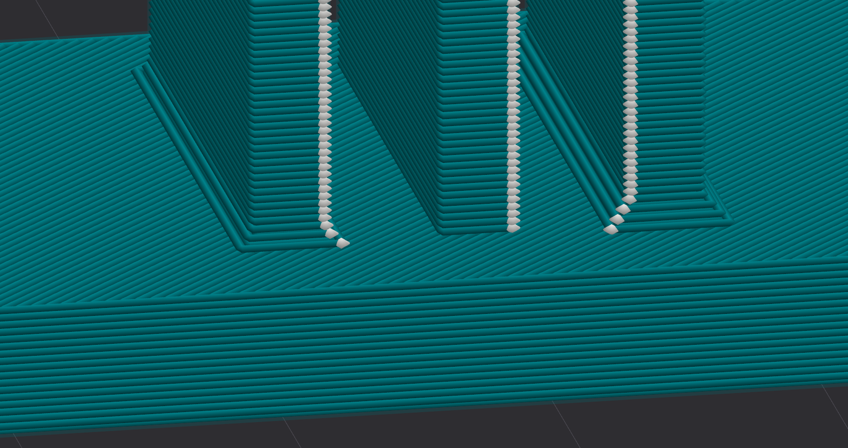
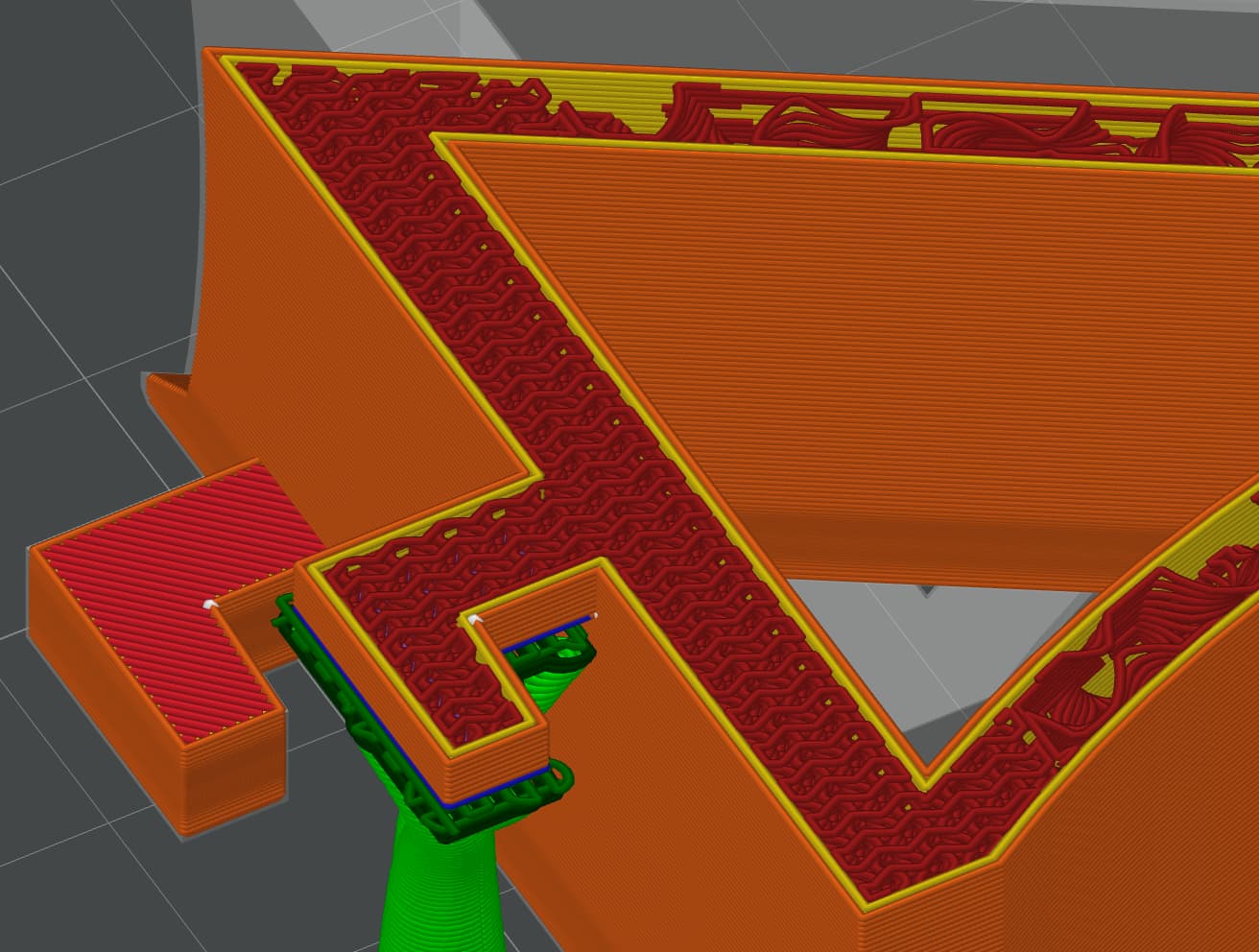
When you say “it is putting it on top”, is it because the slicer is putting a flat base on the transition between the plate and the hinge? That’s normal behavior for the slicer because of how it builds the print layer by layer. I think it is probably stronger on that connection than if it didn’t put a flat base. If you want it to look and be more tied together, turn on it on its side so that the hinges are parallel to the print bed. You won’t see that flat solid layer between the hinge and the plate. Of course, you’ll need to turn on supports to be able to do that. BUT the connection between the plate and the hinges will be stronger because they are tied together. They would share common layers and the lines of filament would extend continuously between them. Here’s the slicer view of my bracket. You can see there is no flat area between the hooks and the back plate and the denser infill flows continuously between them.
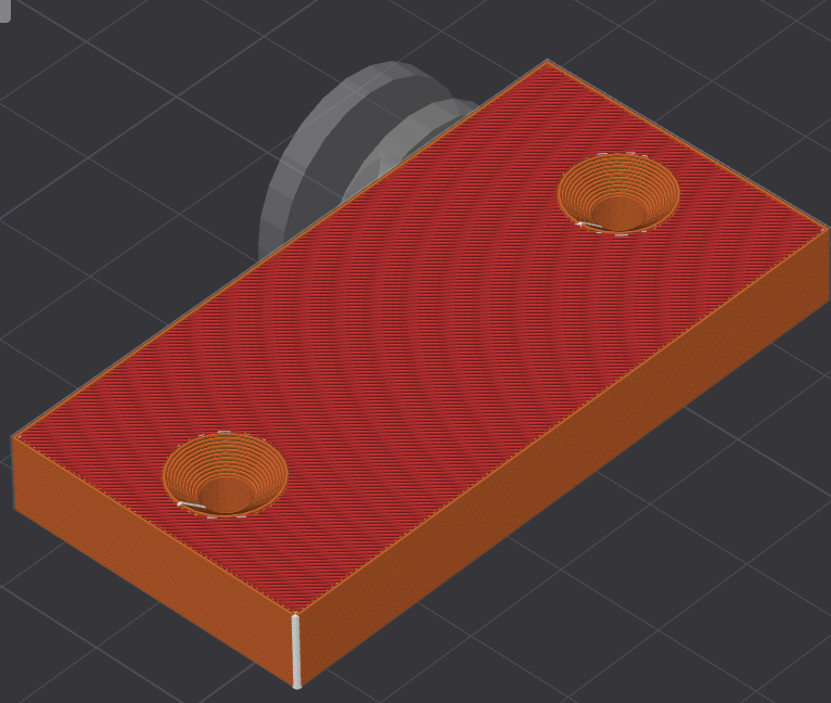
Assembly parts only: Not working. Inside structures are still optimized away.
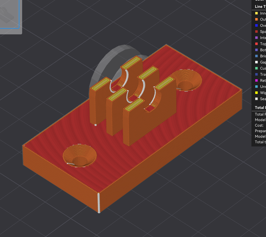
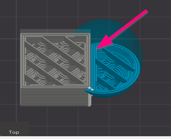
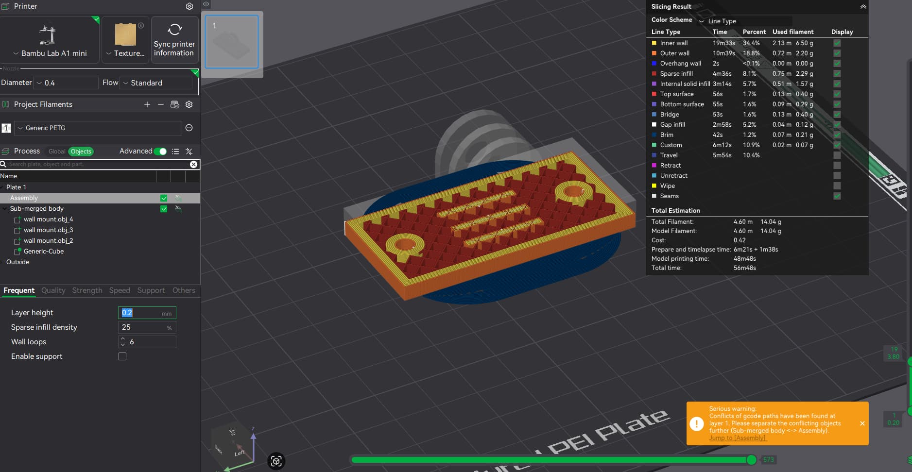
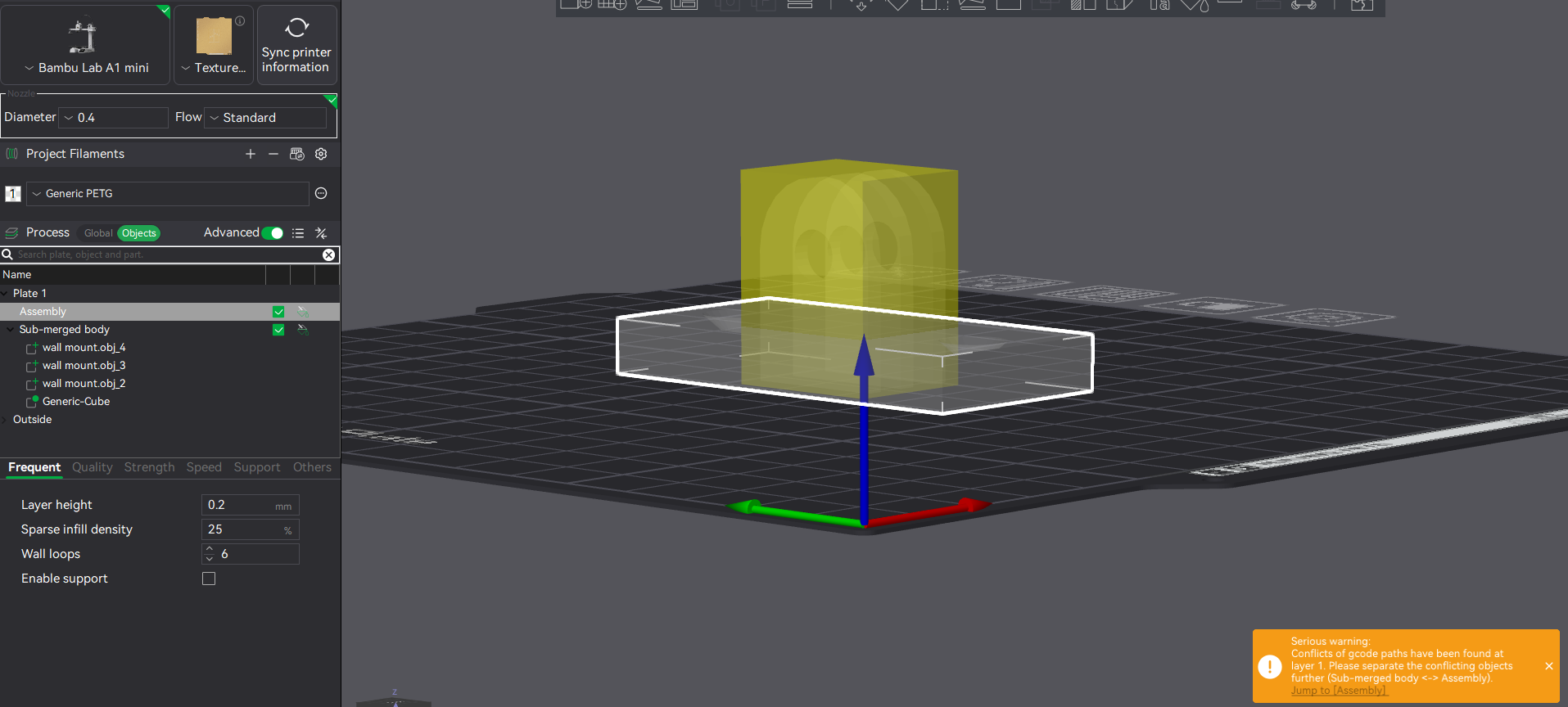
Assembly Submerge only hinge parts: Inside structures are now as I want them, but there is a conflict between walls/objects and a huge mess on the plate → the blue filament?!
Assembly Submerge only hinge parts + modifer: Inside structures are now as I want them, but there is a conflict between walls/objects and a huge mess on the plate → the blue filament?!
Lot’s of good stuff to try out. But I can also see we share the same “colliding walls” issues
About the chamfers - I agree they could assist - I probably ad those later when I get around the printing issues somehow - but it is really more about the fundamentals of the slicer optimizing too much and not being able to control it better that frustrates me.
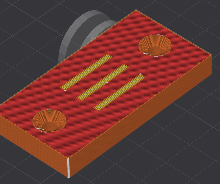
Result is good! (WTF!) If I add chamfers also, it should be really good.
Still wondering about the warning though. In some situations the issues addressed by the warning might be a problem for printing - I believe I have seen this on another print, the failed due to similar challenges and warnings.
Still has a few tricks from the other posts to try out before concluding on a solution.
Sometimes - and I do mean sometimes - I’ve been able to get around the warning by slightly moving the object on the build plate, just enough to trigger a re-slice. In other cases, I’ve had to rotate the object entirely. It’s all trial and error at this point, and honestly, I suspect it’s a bug in the software.
If I could reproduce it reliably, I’d submit a proper bug report. But until then, trial-and-error seems to be the only workaround. Not ideal, but it’s something.