Hi everyone, the problem that I’m currently facing has been a very common issue with all other slicers but since bambu studio is by far the easiest and by my experience the most robust of the bunch I wasn’t expecting it to fail this stupendously… well maybe it’s just me
I’ve tried to add pauses on layers in order to insert hex nuts and while I was fully aware of the problems associated with printing overhangs I was still surprised when I saw that by default the slicer decides to start the print over the completely unsupported and non bridged area by extruding the inner wall mid-air. This seems like a fairly simple implemetation using a check if there is any plastic on the previous layer and/or if the user selected to use supports (even though it would be redundant).
There is also a very elegant way of starting an overhang in this scenario by forming a polygonal shape starting rotated by 45 deg to the original and then proceeding to form the inner skin area. (in red).
Is there a way to change this behaviour since the only way of changing the print order that I know is global or object-based and not layer based. I find this hex nut embedding very useful and an integral way of making robust connections at least for my usecases. I would really dislike having to put a chamfer or a slope in order to mitigate the issue since the light-blue “bridge” extrusion line works perfectly and the only thing failing, and quite frankly destroying the integrity of the print by dragging the unnecesarry plastic around, is the blue “overhang wall” extrusion line.
I’m really looking forward to some ideas from you guys and possibly some recgonition from the developers themselves. Also any help or workarounds in this issue are very welcome. Thank you in advance guys
First. Damn nice post my friend. Very thorough and complete.
To answer your question. I embedded objects in my prints all the time. Sometimes just to add weights or ballast to an otherwise light weight object. I’ve not run into your particular issues so far but I rarely use the default settings. There’s a couple of settings that you might try to change the path of the nozzle. Here are two I might suggest.
In my experience, I never use the default grid when I am embedding objects. Primarily it’s because that pattern provides least strength and when I am imbedding an object, I want it to have something to brace against. Honeycomb is the minimum but for taller objects I’d used adaptive cubic because of it’s greater 3 dimensional support.
Also, it’s a good idea to increase your wall count too. That will impact the strength of the part your gripping. I see in your example you have it set to 3. Give 6 a try and see if that helps. Here’s an example of a print I did for a weighted soap dish where I embedded steel ball bearings for ballast. In this case I used 50% cubic infill with 6 walls.
Of course, don’t forget to check the travel path if you want to see what the nozzle path will be at your layer. I might recommend these settings to declutter the image so that you can focus in on where the head travel is going to be. This at least will save you time and filament before you commit to print.
First of all thank you for giving me a very nice response to my first forum post…well, ever!
Secondly I really have to emphasize that I have a lot of experience with cura with my previous printer (very, very sh***y printer from china) and I have probably used every possibile setting on it followed by eyeing the print for hours untill I could see the effect of probably all of the experimental features. I also used to use prusa slicer and ideaMaker on a Raise3d pro3 plus at work which was surprisingly bad also… This slicer and printer is amazing really and it’s the only one which can actually print things hassle free.
You are definitely right about the infill type but I was trying to minimise the material used and to save some time as well. Also honeycomb is the preferred infill for my case since I was making columns and the honeycomb is a structure used in crumple zones on some Formula SAE cars I’ve seen so i guess it’s really good at taking high axial loads.
I can see that you embedded objects in the infill and then encapsulated them completely which I think makes it easier since the slicer automatically bridges them completely. The problem arises when you leave a hole like I did for the screw to exit the nut.
I have changed some settings today again for another part of the same project and found that the only option that gives me any better extrusion line is the “outer/inner/infill” and it shows some baaaad behaviour at the overhang.
As you can see it literally stops extruding where it needs to and starts extruding where it absolutely should NOT. EDIT: I made a mistake; the yellow line is the Inner wall not the Wipe path and I thought that it’s not extruding there, so all is good even though I wouldn’t call this a real fix since it is changing everything globally.
I will definitely consider adding wall thickness for similar structural parts and a travel path is a nice reminder since I’m starting to see some ghost movements that look llike gap filling but whitout any visibile extrusions in the preview.
OK. I missed that part. I presumed that when you were printing, encapsulation was the objective. Please make sure I’m interpreting this correctly, you’re trying to encapsulate a metal nut and leave the thread hole open?
The only thing I can think of that maybe you might try is to select the feature of “avoid crossing walls” and see if that changes the behavior. Have you tried that?
Another option that I found helpful is to split the model in half and press-fit the nut in after the print. This has two big advantages. First, swaging in a press-fit nut into plastic will likely produce the strongest bond you can get short of over-molding or heat press. Second, it allows for hex-bolts to be added as easily as hex nuts, which was the genesis of the idea to do this in the first place
Here’s an example top and bottom of a knurled nut I did for a replacement part. Note that one has to glue the two pieces afterwards but I used a dowel setting in the slicer which created such a perfect fit once glued that it was virtually impossible to detect that there was a seam. It is important to note that I used a smooth bed for this on the bonded sides as textured beds prevent that near airless gap interface. The dowels were used purely to align the knurling perfectly thus adding the illusion of seamlessness.
This is the cement I used. Note that this is a solvent-based product that dissolves thermoplastics and creates a bond between the combined materials just as if one were welding two pieces of metal together using arc welding other than it works chemically throughout the entire surface whereas heat welding only works on seams.
When I tested this, I took two 100% infill parts and clamped them together then let them cure overnight. I then put one end in a vise and took a pair of locking pliers to pry them apart. The weld was stronger than the surrounding plastic, the plastic failed before the weld.
Note the keyword you should search for is “Thermoplastic cement”. This is the same solvent-based process used to weld PVC plumbing pipes and is made by the same companies. One doesn’t have to use this particular brand.
I faced the same issue with some prints and unfortunately couldn’t find a solution as well.
In my case I can use supports to compensate for it although the distances could easily be bridged.
Seems like Arc Overhangs equivalent features need to develop more.
Hey, sorry didn’t see your post earlier. I’ve “solved” it by just using a different print order in my case but it’s a workaround to say at least. I hope the developers pick this up since it’s quite unlogical.
I wonder whether maybe it’s because of a disconnect between the sliced height and the height at which you want the bridging to happen. i.e. maybe you want the bridging height to be a whole number multiple of the layer height? If it’s fractional, maybe it throws the slicer off. Roundoff error perhaps.
Not sure if that theory holds water, but you could test it by adjusting your model. Or you could try slicing with different layer heights and see whether the problem persists that way.
I might be willing to try it for you, but you’d have to post your model somewhere so I could recreate the problem. I’m not willing to start from scratch and only hope I can recreate the issue before solving it, as there may be obscure print settings you have enabled that I don’t.
Thanks, I have changed the print order as a workaround and it did the trick. However it would be nice if changing the print order was available as a modifier option. That way only the inserts print order would be inverted, but the rest of the part would print with the default print order.
I’m stuck on this same issue. In my case, I’m embedding ball bearings. I put a pause in, drop in the bearing, and I have the wall order set to Outer/Inner, but what it does is print the outer, then prints the inner where it has no connecting support and fails (it doesn’t show that in the print preview, it just shows the layer complete). If I could get it to truly print Outer all the way to Inner (instead of alternating) it would be sufficiently supported. The hack I’m doing now (which I hate) is to take a thin piece of paper, cut it to the bearing diameter and use contact adhesive to stick to the bearing, so that when the printer prints out in space it sticks to the paper. Once the print is done, I dig out the paper but the print itself is successful. In the picture you can see the white disc - that’s the paper over the top of the bearing. Well, you would see that but when I try to add a picture it says “you can’t insert media items in a post” (nor can I edit my post) WTF?
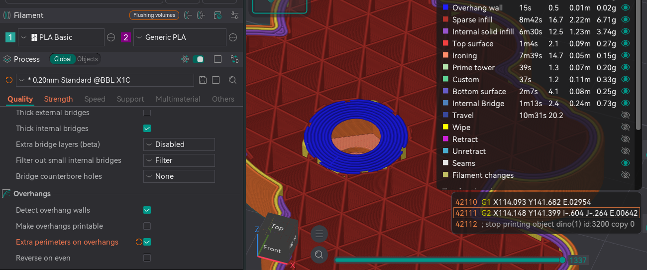
I had exactly the same issue. Only fix I can see is to use the “extra perimeters on overhangs”, but it’s only available in OrcaSlicer. It’s in Overhangs section of Quality tab (enable advanced options).
Hopefully they will add it to Bambu Studio for this exact reason.