Well, you raise a good point. The capture device would have to be self contained with power on board. Perhaps high discharge current (10amp or greater) Lion or LifePo4 cells would do it? Assuming (a big if) the TEC could cool down fast enough, it wouldn’t have to run for hours, just long enough to get the measurement. Or maybe you power it with wires until it gets near where you think the temperature will be, disconnect the wires, then tare and rely on the battery to take you the last bit of the way?
Fortunately, as a first pass grok analysis, it sounds like it could happen fairly fast, but might need 3 or 4 cells (depending on battery chemistry) to reach the target 12v:
Air at 20°C with a dew point of −25°C..
A two-stage module (TEC2-25408 or TEC2-19006) reaches −25°C on the exposed face with margin to spare. A single-stage TEC1-12706 can also do it if the hot face is held within about 5°C of the 20°C air; a typical air heatsink that runs 8–10°C warm leaves the cold face a few degrees short.
Pull-down: 50–70 W
Hold, current-limited: 40–55 W
The face crosses 0°C in under a minute and reaches −25°C in about 2–4 minutes. It stays there. The air an inch away remains near 20°C.
So, let’s say we pick Lithium-cobolt to keep it at 3 cells. Unfortunately, you’d have to include that weight on the scale, which might make detecting a small weight change harder.
Best case: get close using wires, disconnect, tare, and use smaller batteries for the last minute to cross over the finish line.
My big worry was the scale being able to discriminate a small weight change.
Are those already a thing we can already buy for measuring dewpoint, or does it require some diy construction? If it does the job accurately and costs less than $100 and is COTS, that could be promising. I’ve never heard of it before, so I wouldn’t even know where to begin in looking for one. Have you found some?
I looked but didn’t find any right off. Where I got that quote was a 2022 review paper but SAW devices have been around for some time. And the circuitry is pretty simple.
But it’s a search term to use. SAW devices were tried with all sorts of coatings to get mass changes. There were some experiments listed with sol-gel coatings which I’d bet aren’t stable at all and no idea the pros/cons of the different coatings used for humidity.
Anyway, finally tested out the Adafruit library on the SHT45 to see if I could enable the heater. God bless nerds (a term of endearment).
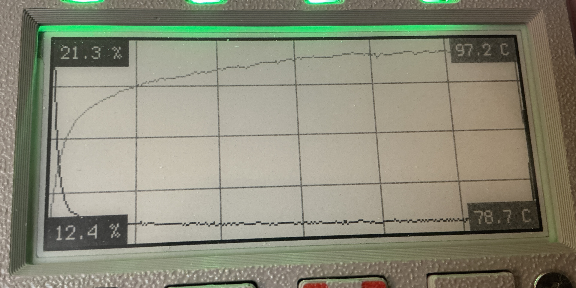
While the settings I needed to run the heater at any setting above the “dry condensation setting” weren’t in the programming environment flyout that is supposed to tell you what commands are available (the low and no heater commands are there), I managed to guess the constant variables they used to get the other commands. Totally logically assigned. So didn’t need to code dive and was able to do this - note the sensor is almost at 100C.
The SHT is pretty cool about how it runs the heater. I was planning to one-shot it where you initiate a cleanse and then it handles it. That’s already how the heater works and you can set 100ms, 200ms, or 1 second but that’s it. So if you want to heat for longer (like the hour for removing VOCs) you have to retrigger it yourself and be mindful that you don’t overtemp it. But that’s easy and you can use the sensor itself to keep tabs on the temperature.
Added - it might not be obvious what’s going on but the software set the heater to high for 1 second and started a free-running data acquisition to fill the data arrays used for display. Turns out by accident that the free-running data acquisition was the perfect duration to capture the heater effect. I had been running the heater in different modes so the starting humidity was a fairly low 21.3% to start but fell to 12.4% (the dark line that decreases rapidly at the start). The temperature (lighter gray line) climbs from 78.7C to 97.2C from the heater action. You can just barely see the humidity start climbing and the temperature crash at the far right of the display as the heater turns off again. Perfect data capture that was totally by accident that it worked so well.
Update - Did an hour bakeout of the sensor at 80C first half hour and 100C the 2nd. Retesting that same spool and I’m getting 16.6%RH which is the same as it reported yesterday (except I didn’t note the tenths value). Even if the bakeout was only partially effective I would have expected some difference in the reported value. I’ve got a third brand of sensor but it’s hiding from me right now. As soon as I find it, I can dunk it in too and see what three different sensors all say and if any two agree. The little round sensor is holding at 10% while the SHT45 is saying 16.6%. The round sensors agreed among themselves when I got them. I spread them out on a table and let them settle. There were just a few a single % off from the others.
It turns out that for both the SHT and HDC chips you can’t get one that has both the PTFE filter and the protective cover on the same chip. It’s one or the other, or neither. i.e. three types. So, what to do if you want both the PTFE filter and protection? The sensiron datasheet specifies a particular low tack Kapton tape to use to make your own cover to place over the chip top during reflow, washing, etc. to protect against VOC contamination. Then peel it off afterward.
So far, though, it looks like there wasn’t contamination at least as far as the heater can clear. Response after baking the sensor is exactly the same as the test before as best I can tell. I wasn’t saving off the data to be able to compare actual data but I suppose I could.
I still haven’t found where I put that other hygrometer but the humidity change had just slowed at the 16.6% point. It’s still coming down and was 15.8% when I checked a while ago. I haven’t swapped the sensor out with another one yet but that’s next. It will be interesting if it behaves the same or not.
Both are with the PTFE membrane. That may have been a mistake to get that version since this one at least is taking so long to equilibrate. Response is slow. I bet I can lift the PTFE out or cut it out with an X-acto blade though and that it will make a difference in responsivity. But maybe it’s the sensor element itself that’s slow. Will know that when I remove the PTFE and test again.
I checked at Adafruit and unless I missed it, they don’t say if they use the sensors (SHT40, SHT41) with covers or not and it’s not available as an option. They don’t show covers in the photos. The only option is the PTFE like you note on the SHT45. Not familiar with other sources except for raw chips.
Update - just swapped in a different sensor and it went straight to 8.5% and is already at 7.7%. So that original sensor is possibly bad for some reason. Or at least that’s how it’s looking. I’ve got one more SHT45 I’ll swap in next and see how it does. I’m guessing that this now agreeing with the round sensor that’s bottomed out at 10% is pointing at it being a bad sensor.
I have a SHT35 demoboard from Sensirion. The sensor is also completely off and I’m sure, that they take care to solder it correctly. So it seems to me like it got damaged somehow in use. Would be good to know what can cause it.
Hard to say but it wouldn’t surprise me if it was me that hurt it. As I was working on code and housing it saw a fair amount of handling and part of that was without a housing. But it still works great as far as communications, heater, and responds as I would expect except for an offset. It works. So this one may have something odd with the sensing element itself and maybe nothing to do with any handling I did. But I don’t know.
The one that seems to be working properly came right out of its bag and the next one I was going to try is still factory sealed.
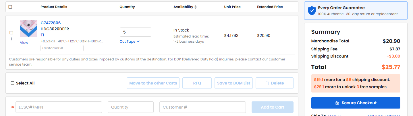
These are identical to the HDC3022’s that we were talking about earlier in this thread, except that they lack both PTFE and also the protective cap. Why 5 and not 1? It’s the sweet spot because of their pricing structure. The incremental unit cost for the extra four was only around $2.50 each:
I’ll apply the low tack Kapton specified in the Sensiron datasheet, or if TI has specified something different I’ll use that. Then I’ll just solder it by hand with a lot of flux and then remove the Kapton cover after the soldering is done and I’ve cleaned off all the flux.
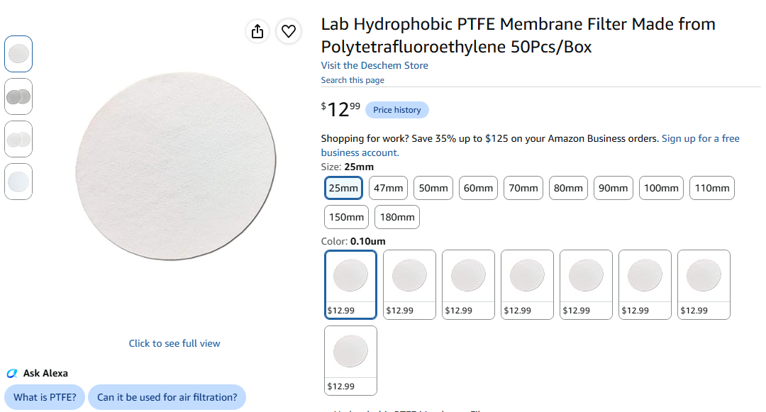
At that point, it would be open port with no PTFE. Option 1: The pore size on TI’s PTFE is 0.1um, and amazon sells scads of the stuff (enough for hundreds of chips) for $12. I’ll design a PCB to have all the passives on one side of the board and the HDC3020 on the other. That way, if I want to apply a filter, I can just mechanically clamp the PTFE over and against the chip on that side of the board with a 3D printed bracket I’d have to design bespoke in fusion360. This avoids trying to glue a seal piece of PTFE on top of the chip using some exotic glue that I’d have to procure in order not contaminate the sensor. Option 2: Just ignore the filter altogether. With five chips, I’ve got plenty spares.
Then just have OSHpark make the PCB’s. Given how small the PCB will be, it will be cheaper and faster than ordering from overseas. If going with option 2, I’d probably just get 3 clones of the Adafruit board for a total of $3.50 delivered:
Nice! Brilliant idea to grab the Adafruit board files! At first I wondered where you were going to get boards, but there you go!
One thing that may not matter for your chips is that center rectangular contact. If it’s important it will be in the datasheet. Since it’s there in the Adafruit board they probably solder it. On the SHT it gets in the board design if you want higher thermal conductivity to the board. Omitting it is better if you will be using the heater. But it’s a deal on the SHT and may or may not be for your chip.
What are you using to drive it? And I just spotted the price! Holy moley! $3.50?
The third SHT45 is agreeing with the second so looks like the first one has an issue. I had the Praki open a little longer while swapping sensors and the first readings were 10.5% but headed down (9.2% now). The reading when I pulled the second sensor was 6.6%.
So much happier now. But response down is slow. I bet response up is quicker but have no data to back that up. Just a hunch.
Yup. OSHpark charges by the square inch, so the delivered cost of tiny boards is quite low.
It’s a reliable vendor that’s been around for years and years. Being domestic, it also provides shielding against all the tariff war craziness. i.e. you won’t get an unpleasant unexpected bill from customs that you then have to sort-out under “stick up” conditions before you can receive your package.
When I was getting boards done even the smallest would be a lot more than that. For the Adafruit-style sensor breakouts, that’s a huge deal with design and drivers already done when you want to control certain aspects of components used on the board.
Sensor 3 is down to 8.7% now. Slow response for sure but also no circulation to speed things up.
It’s the cheapest of what I could find on amazon, but it has a lengthy lead time. Also, quantity 50 is way more than you’re ever likely to need.
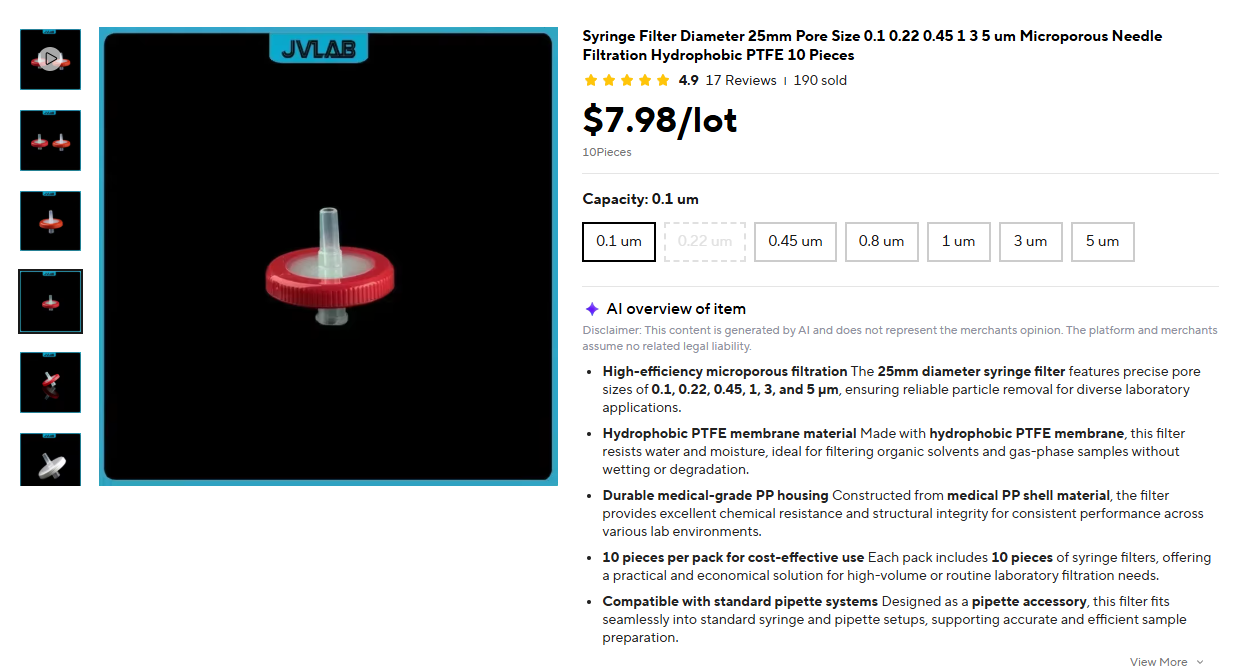
You can buy a smaller quantity, with faster delivery and for less money from aliexpress. Search for 0.1 micron PTFE syringe filters. That’s the same PTFE pore size that TI uses on their chip. The pore size is big enough that TI says it incurs only around, IIRC, about a 300ms sensing latency (if installed by TI on their official chip) as compared to no filter at all. If you install it tight against the chip, without a big bubble of air underneath it, it seems reasonable to expect about the same magnitude of latency from a DIY installation.
Thanks to your comment it just occurred to me that one striking advantage of using a DIY PTFE chip filter that’s mechanically clamped is that if it ever did become dirty or contaminated, you could just unclamp it, remove it, slot in a fresh replacement, clamp it down, and keep rolling. That option doesn’t exist with the canonical factory PTFE chip installation. The DIY solution is more akin to changing the filters on your vacuum cleaner.
I imagine TI’s or Sensiron’s reply to that would be you can likely just dust off your factory installed chip filter, yet your own experience with the SHT45 filter seems to contract that notion. I guess we’ll know for sure if it works without issue after you remove the filter (oh, scratch that, I just re-read your post and you’re not going to remove it. My error. My first read was you were going to remove it).
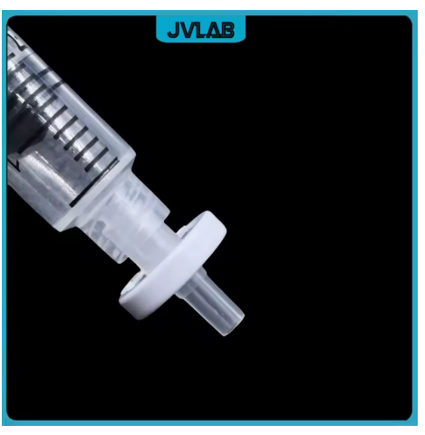
Changed my mind. I think I may have found something even better. For relatively low cost you can buy the filters pre-installed into these handy little holders. So, just come up with a 3d printed enclosure that you squeeze one end of these into, and if you ever need to change it out, you just pop it off and pop in a new one.
With more filter surface area, maybe the diffusion is even faster, though the long-neck is an obvious bottleneck I wish wasn’t there. I’d probably trim that down to the minimum length that doesn’t violate the integrity. And with massively more surface area than the chip installed filter, it would also be more resistant to fouling blockage by dust and other contaminants.
Not sure how it would ultimately affect sensing latency, given the longer travel path. Not sure how to predict that. Would just have to build it and measure it. Even if worst-case it added a minute or two of latency, though, instead of milliseconds, I don’t think I would care. Nothing we’re going to be measuring on the i10 will be changing fast enough for it to matter.
This appears to illustrate how they’re typically used:
Evidently it’s just pressed on to the syringe nip.ple (or whatever it’s called) for filtering whatever liquid gets drawn into the syringe. So, just add an equivalent nip.ple to your Bambulab 3D printed sensor enclosure, and it should fit. Or maybe make it a compression fitting, like a gland would have, if you want it held securely and guard against unintentional dislodgement. Or glue it to the enclsoure, since you can always print a new enclosure. Whatever you deem easier.
Well, maybe not the glue, since that could contaminate the sensor. Better to stick with mechanical clamps, like a gland fitting. Use a silicone o-ring to air seal the connection against dust, or any o-ring that won’t degrade over time and create dust of its own.
Dead volume will get you on those, though. They’ll be super slow to respond. One of the features Sensiron touts is the low dead volume and distance beteen the PTFE and the sensor element. PTFE clamped across the housing would be better but the distance will go up and dead volume too but not like the syringe filter. Also where mine are going is inside the Sunlu so it won’t be exposed to much once the cabinet gets here.
Checked the 3rd sensor a while ago and it was at 7.6% which puts it within the accuracy specification of the sensor (+/-1% RH) with sensor #2 last showing 6.6%.
Dang. i hadn’t considered that. Thanks for point it out! I think you may be (probably are) right.
Well, I’m out of ideas. It’s back to either clamp it against the chip or go naked. Too bad: the idea of the little pod-like thing as the solution was really starting to grow on me. But better to recognize a fatal flaw now than fail later.