I have officially filed a Provisional Patent Application (PPA) for a logic-based system to automate functional 3D-printed enclosures. I am releasing this logic under the GPL (General Public License) to ensure it remains an open standard for the maker community.
Status: Patent Pending (Filed May 4, 2026, 2:40 PM ET)
As a mechanical engineer with a background in product design, CAD, and extensive experience with amphibious ATVs and aircraft walk-arounds, I’ve seen how ‘simple’ parts often fail in the field because they lack environmental adaptability. I developed this system to move our slicers from ‘static scaling’ to 'functional adaptation’
I’m looking for developers to help script this into a Bambu Studio plugin. If the architecture here is too closed, I’ll be looking to the Prusa/Orca communities to ensure this becomes a standard tool for all.
Why this matters:
Most current slicer tools offer simple scaling. If you scale a pump filter, the mesh holes might become too large to stop debris, or a cord grommet might become too small for the wire. My “Bushwacker” logic solves this by making the geometry aware of its function:
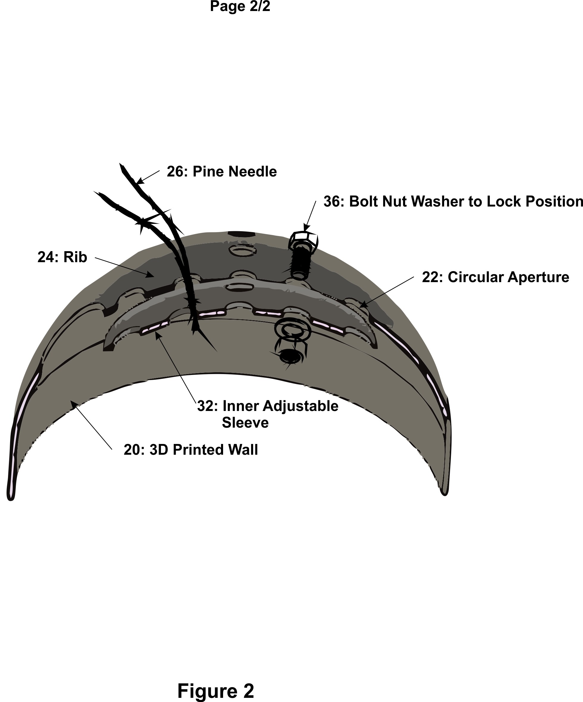
“Needle-Gate” Filtration (Fig 2): Uses a debris-diameter logic rule. It doesn’t just make holes smaller; it creates an anisotropic constraint that prevents linear media (like pine needles) from orienting with fluid flow.
Bioregional Moiré Adjustment (Fig 2): A dual-layer sleeve system (32) that allows users to manually “tune” filtration density for their local environment before locking it with a standard fastener (36).
Automated Asymmetric Ports (Fig 1): Automatically calculates the elliptical projection for off-center discharge vectors (12), generating the correct geometry for TPU vibration-isolation grommets.
Procedural Riser Extension (Fig 1): A “Z-Axis” logic that adds a 25mm skirt (16) to increase internal volume without losing the original dome’s structural integrity (14).
I want to see these logic rules integrated into Bambu Studio as a “Functional Enclosure” toolset. I am looking for developers to help bridge the gap between this engineering logic and machine-executable code. If we can’t make it happen here, I’ll be taking the framework to the Prusa and Orca teams to ensure the community gets these tools.
It sounds like an interesting “best guess” auto adjuster for xy contour/hole compensation to keep up with an implied tolerance also getting scaled. Whatever you come up with better show up in the slicer in an obvious fashion or people will be very mad. There’s a reason that “make overhangs printable” feature has like 3 alerts to click yes through, altering geometry introduces otherwise impossible errors.
But reading the specific examples and pictures I think this is just ai garbage. Maybe from the start lol
Just hop into Onshape and you can do all that today.. Even clunky old CADs like SolidWorks can work if you’re willing to tolerate a few crashes and writing some macros.
This is a CAD function that every parametric modeler worth it’s “salt” does already. IMO the slicer is not the place for doing CAD work. Basic stuff that a typical hobbyist might want to do, sure. You can scale and do simple CSG operations, apply text. But making a slicer even more “heavy weight” to compete with CAD tools specifically built do perform these kinds of operations doesn’t make a lot of sense to me.
CAD for design (like Fusion), CAM for production (like Studio). Never the twain should meet.
There’s some overlap at the intersection of the Venn diagram, but it’s not a huge amount nor should it ever be… If you need to make design changes, the best place to do that is in CAD with the original source and everything linked in a hierarchy, not in a slicer where it has to guess because the parametric relationship between features has been lost in translation.
Corner cases where all you have is a STL and you need to scale the object but not the holes for screws, something like that, probably exist. But for serious engineering, I can’t imagine someone would think making the modifications in the slicer was a good idea. Legitimate engineers will have the original CAD files and will make their changes there.
I appreciate the mechanical skepticism—that’s exactly why I’m looking for collaboration from the ‘Code Guys.’ You’re 100% right that altering geometry blindly introduces impossible errors. That’s precisely why this isn’t just a ‘best guess’ auto-adjuster; it’s a framework of fixed constraints.
To address the ‘AI’ comment: This comes from a 25-year career in mechanical engineering, specifically working on product design, amphibious ATVs, and aircraft. The sketches (Fig 1 & 2) were drafted in Corel and represent the logic I’ve officially filed with the USPTO under my PPA as of May 4th.
The goal isn’t to have the slicer ‘guess,’ but to have it execute a specific Parametric Logic that I’ve already engineered. For example, the Needle-Gate isn’t an ‘xy compensation’—it’s a conditional mesh generation where the aperture is a slave to a user-defined debris diameter.
I agree with you on the ‘alerts’—any tool like this would need a clear ‘Preview’ and ‘Accept’ workflow to ensure the user sees exactly how the riser or the moiré sleeve is being generated before the G-code is sliced."
You’re right that this can be done in parametric CAD—that’s exactly where I developed it. However, the goal here is to remove the ‘CAD Tax’ for the end user.
In my experience as a mechanical engineer (working on everything from product design to amphibious ATVs and aircraft), the field-level adjustments—like changing a discharge port angle or tuning a filter for local debris—often happen at the point of manufacture.
By moving this logic into the slicer, we achieve three things CAD can’t easily do for the average maker:
Accessibility: A user doesn’t need to master Fusion 360 or OpenSCAD just to adjust a pond filter for their specific regional needles (the ‘Bioregional Moiré’ logic).
Speed: It turns a 30-minute CAD redesign into a 10-second slider adjustment in the Slicer GUI.
Non-Destructive Scaling: Standard scaling ‘breaks’ functional features (like mesh density or grommet fits). Slicer-level logic ensures the part remains functional regardless of the scale.
This is about evolving the slicer from a simple G-code generator into an intelligent manufacturing assistant."
I completely respect the ‘CAD for Design / CAM for Production’ workflow—that’s the standard I’ve lived by for 25 years as a mechanical engineer. You’re right that for a massive industrial project, you go back to the source.
However, I’d argue that what I’m proposing isn’t ‘Slicer-CAD’; it’s Intelligent CAM.
In high-end CNC machining, the CAM software is increasingly aware of the geometry’s intent to optimize the pathing. What I’m proposing is that the slicer (the 3D-printing version of CAM) should be aware of the functional intent.
Take the Needle-Gate or the Bioregional Moiré:
In traditional CAD, if I change a filter density, I’m re-sketching patterns.
With this logic in the slicer, I’m simply adjusting a manufacturing constraint.
As for the ‘lost in translation’ point: That is exactly why I’ve developed this as a logic-based framework. The slicer isn’t ‘guessing’ at an STL’s history; it is applying a new, procedural layer of geometry onto the mesh based on engineering rules.
We’ve already seen the ‘Twain meet’ with things like Bambu’s text tools and primitive Booleans. This just moves that needle from ‘Basic Hobbyist’ to ‘Functional Engineering.’ Why force a user back into a heavy CAD environment for a 2-minute field adjustment that the slicer is mathematically capable of handling?"
I don’t quite think you are explaining yourself well to anyone but the patent office for any of the words or images you wrote after the following sentence: “…that allows users to manually tune filtration density…” << you’re using implementation language of an example, and figures from an example that are way too complex to convey what it is doing. It literally has a line on it drawn that says pine needles. The topic is about scaling. You sure this aint AI?
I appreciate the heads-up, but that’s precisely why the May 4, 2:40 PM ET timestamp is so critical.
In the ‘First-to-File’ system, my protection was locked in the moment the USPTO received the application. By filing before sharing the logic on this forum, I’ve legally established priority. This allows me to discuss the engineering logic and seek collaborators under the GPL license while preventing a third party from taking the idea and filing their own claim tomorrow.
It’s a defensive move designed to keep this logic open-source for the community, rather than letting a corporation lock it behind a paywall later."
I’m a big fan of Onshape and I live in Fusion 360 for my primary design work. You’re right that we can write macros or build complex parametric assemblies to do this today.
But here is the challenge: If I share a ‘Smart Pond Filter’ with the community, I don’t want the user to have to ‘hop into Onshape’ just to adjust it for their local debris.
My goal with the Bushwacker logic is to move those ‘macros’ out of the design environment and into the Slicer UI. This creates a ‘Productized’ workflow where:
The Designer (like us) sets the engineering constraints in the logic.
The User simply adjusts a slider in the Slicer to fit their real-world needs (like the Needle-Gate mesh or the Riser height).
We shouldn’t require every maker to be a ‘Power User’ in SolidWorks just to get a functional, adaptive part. This is about making the Slicer do the heavy lifting that is currently trapped inside expensive or complex CAD software."
There’s also the argument to be made based on legislation that’s going around the US that it should be very clear at which levels of the process there is (or can be) any awareness of the functional intent of a design. Most of the folks in this forum are aware that the printer itself has no clue what it’s printing and is completely incapable of knowing that (printers are way too primitive creatures). The next level up is the slicer and that doesn’t have any knowledge of design intent either. Of course once you get to the CAD system the thing being modeled is rather clear.
I want to make it clear that I have no interest in making any of the things that new legislation is trying to catch, but I want it equally clear that we’re heading for rough times when people make rules based on ideas that a printer can understand design intent when it can’t.
I’ll take the ‘too complex’ comment as a compliment on the draftsmanship. The reason there is a line drawn for ‘pine needles’ is because that is a real-world failure point I’ve encountered and solved.
If you’ve ever had to clear a pond pump intake in the middle of a storm, you know it isn’t an abstract ‘scaling’ problem—it’s a physics problem. My ‘implementation language’ is specific because this isn’t a vague concept; it’s a filed functional logic for a TPU-based dome filter designed specifically to reject linear debris like needles and leaves.
To simplify it for the thread:
Standard Scaling: You make the filter bigger, the holes get bigger, and the pine needles get through.
My Logic: You make the filter bigger, but the Needle-Gate logic (Fig 2) keeps the aperture fixed to the debris size while adding more surface area.
As for the AI comments—AI doesn’t file PPAs with the USPTO. I did, on May 4th. I’m happy to move past the ‘is it real’ debate and talk to anyone interested in the actual G-code math for the Bioregional Moiré."
If you have a functional housing for a water pump and you switch to a taller model, standard scaling in a slicer would distort the entire object, making the filter mesh too large and the structural ribs too thick.
With the Riser Logic (Fig 1), the slicer identifies the base and simply ‘extrudes’ the vertical walls by the extra 25mm needed to clear the new pump height. The rest of the engineering—the dome strength and the Needle-Gate apertures—remains identical.
This isn’t just about ‘printing a sieve’. It’s about a Procedural Toolset that allows any functional enclosure to adapt to its internal hardware (pumps, sensors, connectors) without the user needing to touch a CAD program. The PPA I’ve filed covers this logic as a universal slicer enhancement."
I appreciate the honest exchange, Bullocks. It’s easy to be skeptical in the age of ‘prompt engineering,’ so I’m glad we could clear that up.
Now that we’re past the ‘is it real’ phase, I’m eager to hear from anyone else on the Technical side. If we look at the Riser Logic (Fig 1) for the pump or the Needle-Gate mesh (Fig 2), what are the biggest hurdles you see for a Slicer implementation?
I’m here to provide the constraints and the math; I’m just looking for the right ‘Code Partner’ to help build the bridge."
That is a profound point, sprior, and one I take very seriously. As an engineer who prioritizes digital privacy and critical thinking, I’m well aware of the ‘double-edged sword’ regarding software awareness.
However, there is a key distinction in the Bushwacker logic:
User-Driven vs. System-Driven: My proposal isn’t for the slicer to ‘guess’ what a part is (AI-based recognition). It’s for the slicer to provide User-Activated Tools. The software doesn’t ‘know’ it’s a pump filter; it simply executes a ‘Needle-Gate’ mesh because the user told it to apply that specific geometric logic.
Procedural Logic vs. Content Scanning: We aren’t giving the printer a ‘brain’ to judge content; we are giving the slicer a better ‘toolbox’ to generate geometry. This is no different than the slicer knowing how to generate a ‘Hole’ or ‘Text’—it’s just a more advanced geometric primitive.
The GPL Factor: By releasing this under the GPL, I’m ensuring the logic remains transparent and community-controlled. Open-source logic is the best defense against ‘black-box’ legislative mandates.
We shouldn’t hold back functional progress because of how regulators might misinterpret the tech. Instead, we build the tools to be locally executed and user-controlled, keeping the ‘intent’ strictly in the hands of the maker.