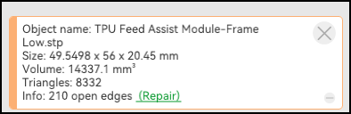
What is going on with this part? While this is a relatively short print, I do not want to have to print it twice by doing something stupid.
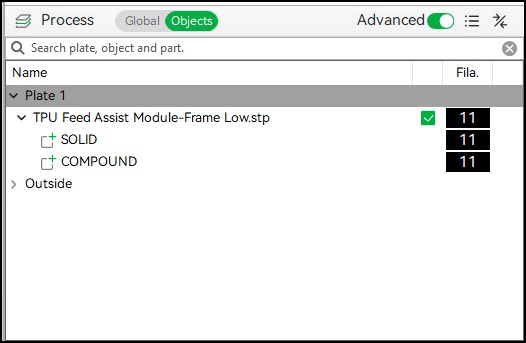
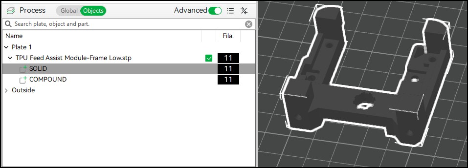
When I import the Frame Low, I show it as a part that is comprised of two subassemblies, Solid, and Compound which are reflected in pictures 2 and 3.
Solid selected which is the Main body
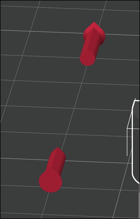
When I choose Compound, there are what look like a set of plugs placed in some holes. I do not understand what is being done here, or why. There are other open holes on the part that printed fine so it seems like there is something else going on with these two locations.
Earlier, I repositioned the part but had selected “Solid” (a sub-part) rather than the assembly and the parts are not just cylindrical shapes.
So, that’s pretty funny… I think I know why those are there, but I don’t understand why they’re not holes…
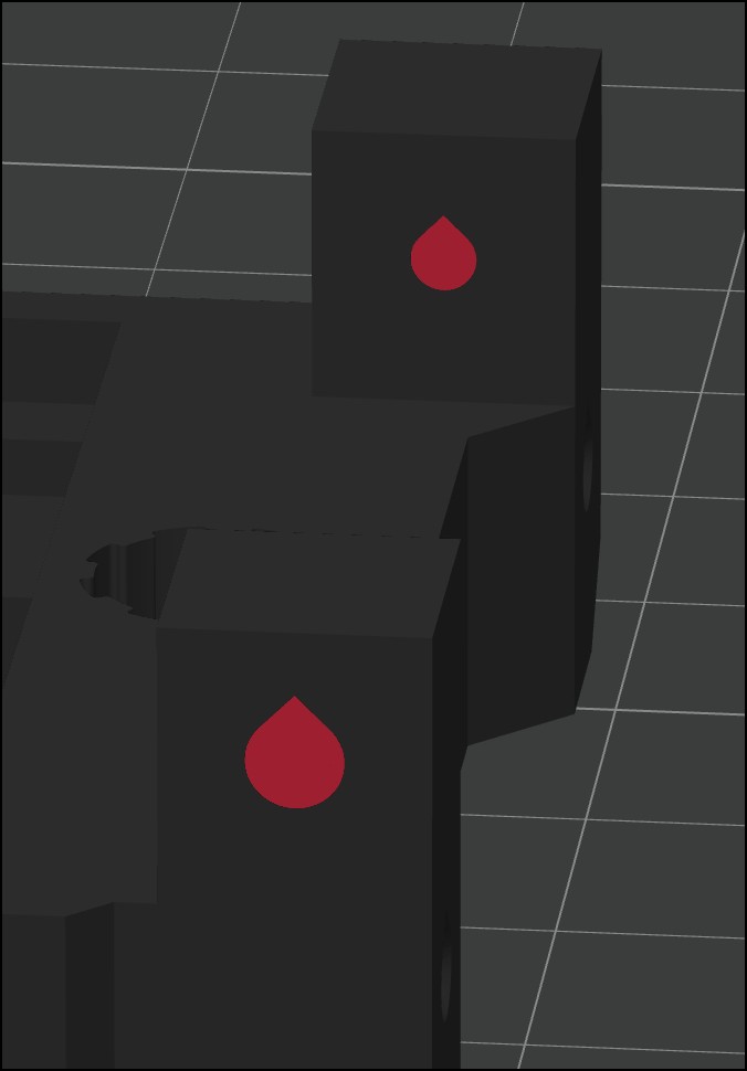
Back when that design first came out, it looked like this:
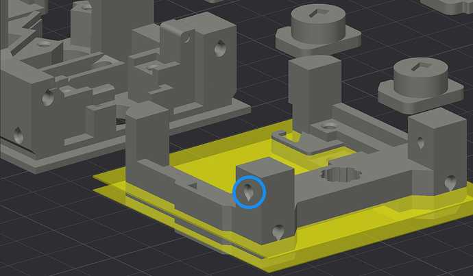
Note the teardrops are upside-down (compare to the part behind). I “reported” this on a thread here and also in the model comments on MW. (It printed and worked fine that way though.)
So I guess they fixed it, or tried to? Are the bottom holes the same way in the updated frame, or still upside-down? (And now I’m not 100% sure those plugged holes are even used… have to check assembly instructions.)
(If you’re not familiar, the teardrop shape is used so the top of the hole doesn’t have a bridge there. For small holes I don’t typically use them anyway.)
-Max
It is only those two locations. That is what motivated me to ask the question. There are holes all over there are two parts that hold the extruder drive. The LOW frame and the UP frame which would be be better named the Upper Frame and Lower Frame and between the two parts there are a ton of holes and only those two have the inserts. Why did they only do that for two of the holes.
It looks like they forgot to remove them as now that I am assembling, screws are supposed to go in those two locations.
All of the files are .stp which I am not familiar with. What CAD/Drawing program uses that file format as it’s default?
Indeed, checking the assy. instructions, they sure are. Very odd that they were plugged in the model, bummer. Can you drill some holes?
That’s STEP format, which is a somewhat-generic/standard interchange format which preserves actual curves, surfaces, and hollow spaces (and in some cases sketches as well). It’s basically “one better” than the mesh formats if one wants to make changes in CAD.
The MW listing does provide project files in 3MF format, “ready to print” so to speak (or literally if one likes their settings).
I agree with CF that Made.In.Meidling’s version is superior on some ways and I probably would have printed that if it had been published already when I got my module, but OTOH I don’t find anything particularly wrong with the BL housing either… not worth a re-print and re-assembly for me.
-Max
I did a little more digging on this and I am inclined to think this is an uncorrected error on Bambu Labs part.
On that particular part, when I import it from the folder with all the parts, I would get this error
This is a SWAG on my part but I kind of think that teardrop shape is some sort of device that the engineers at BL use to make horizontal holes come out better than (WAG = Wild Assed Guess) than just making a cylinder. I have seen various folks on youtube comment on how a horizontal hole is problematic for fdm type printers vs vertical holes. Other parts of the model have that same odd shape on the horizontal holes.
I use cylinder primitives to make holes on models for various reasons and I noticed a while back that they (BL) had added a primitive Double Tear Romboid Cylinder which is an unusual shape (at least to me) but that may be tied to those teadrop sort of holes.