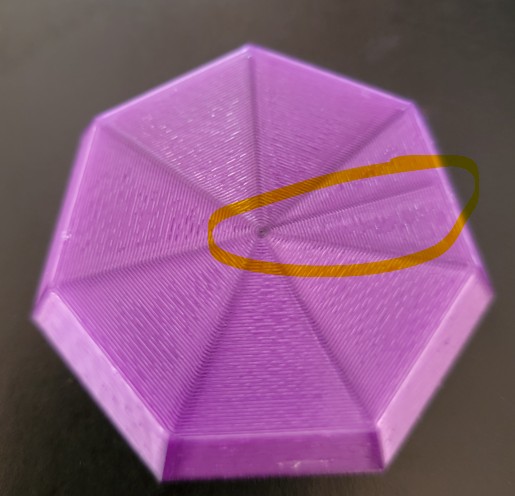
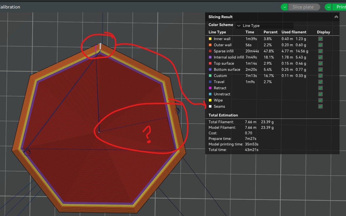
I am trying to do a simple print and I am getting a “seam” in a place that (for my purposes) destroys the print. Note that I have tried all of the seam placement options, as well as seam painting, and none of these have any effect on this issue in the print. They do work to move the seam around, so I am convinced this is not a “seam”. Based on analyzing the slicing result, it appears that this is a movement artifact from the slicing (?). So how can I tell the slicer to NOT do this, or to move the location of this [thing]?
If I had to guess, that’s looks like a misplaced seam and it’s location can be moved in one of two ways.
Rotate the model on the build plate and re-slice to see where the seam is relocated. This is trial and error. You’ll want to rotate it on the plate till the seam reaches the corner where it can be more easily concealed by the model geometry. You can’t really get completely rid of it.
Align With Seam [if painted, random, aligned, back, but not Nearest]
Specify Angle [Advanced, would allow a specific angle of travel to be specified for all internal infill layers, 0° would be vertical, etc.)
[0-359° editable to 3 digit precision ###.### (enabled if parent option selected of course)]
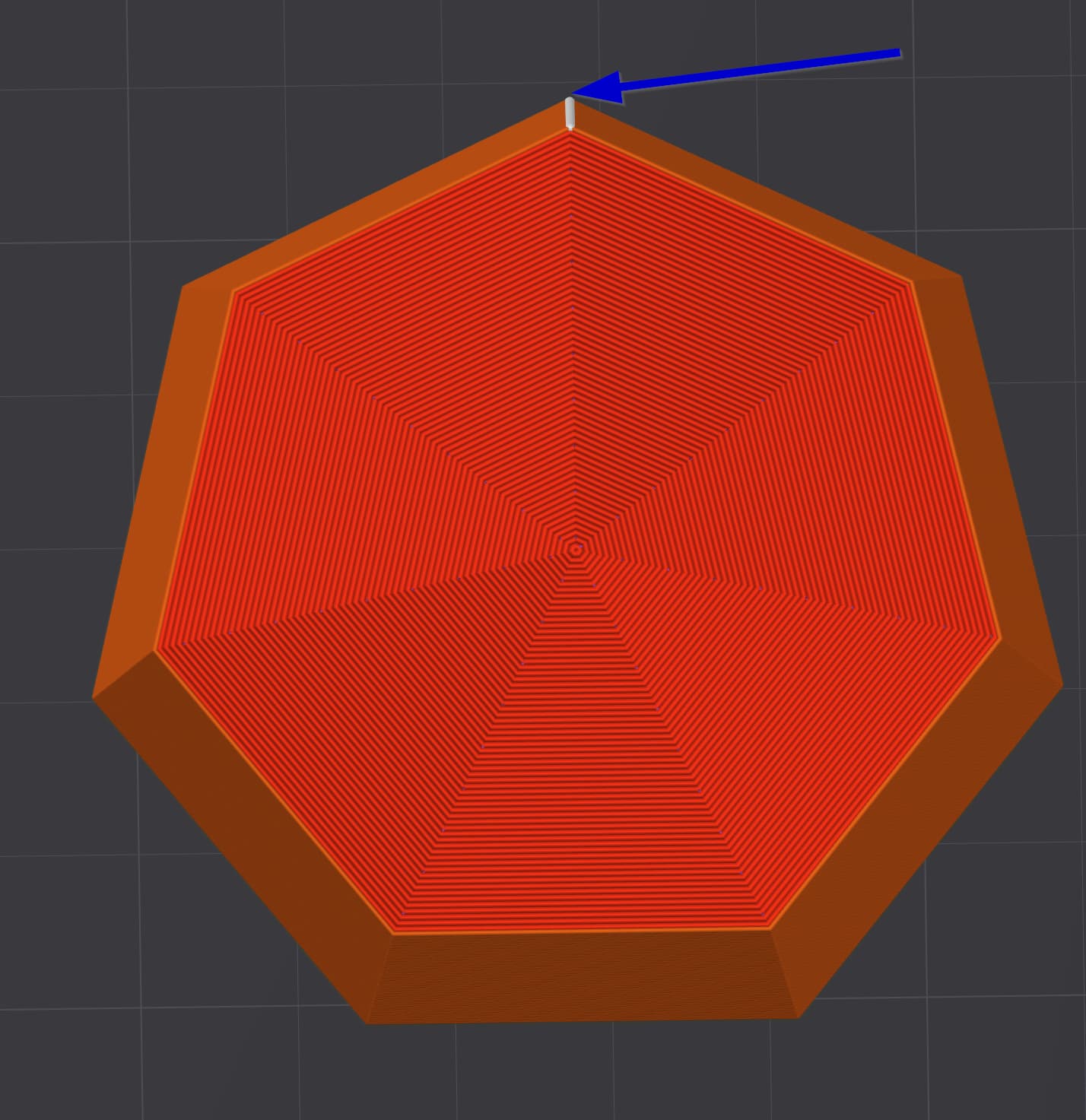
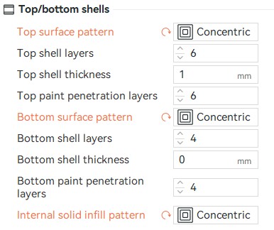
Yes, with no difference. I am assuming that this is an issue, as you say, with the concentric fill pattern. Each concentric path must have a start/end place that does not coincide with an edge, so the slicer chooses the shortest path for the print head in the interest of print speed.
At the simplest level, if the slicer travel to the beginning/end of each concentric shell could target an angle in the calculated shell rather than in the middle of a straight line, that would solve the problem.