Awful and strange printouts

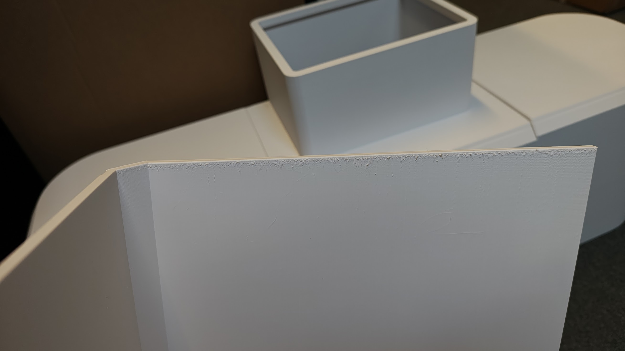
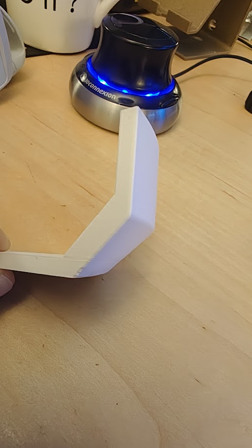
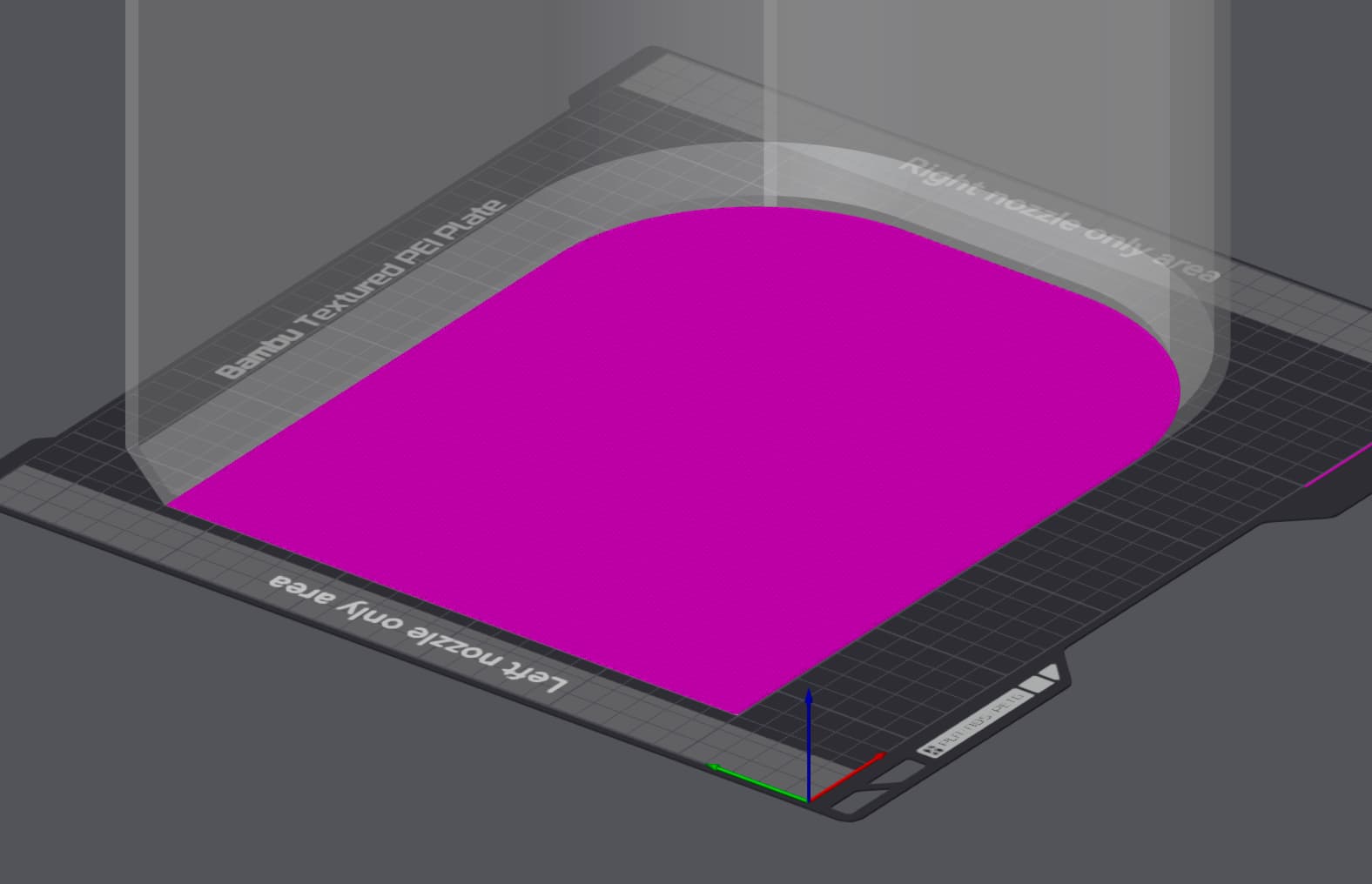
We purchased an H2D for our company. From the outset, we have been trying to print certain components for a new product prototype. We even changed the design for 3D printing because the printer couldn’t handle a radius of 20.


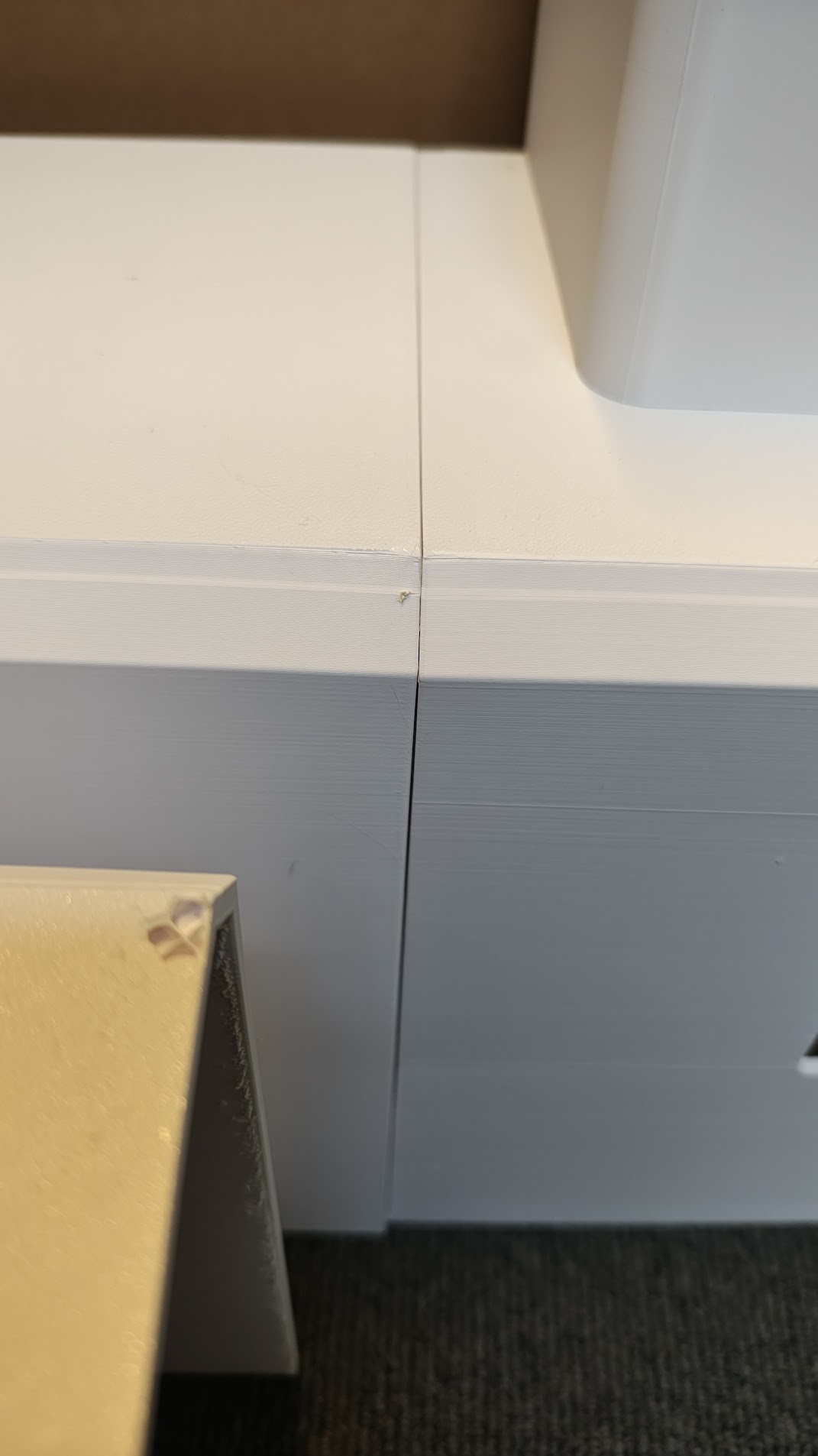
The strangest thing is that I printed a test of a cut-out fragment of the same object, and it printed perfectly!
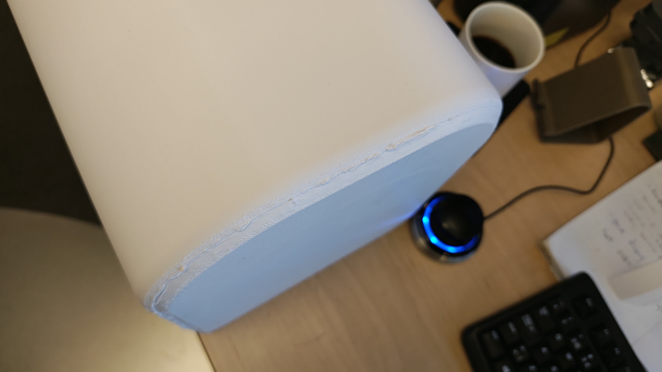
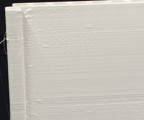
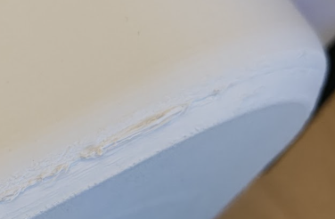
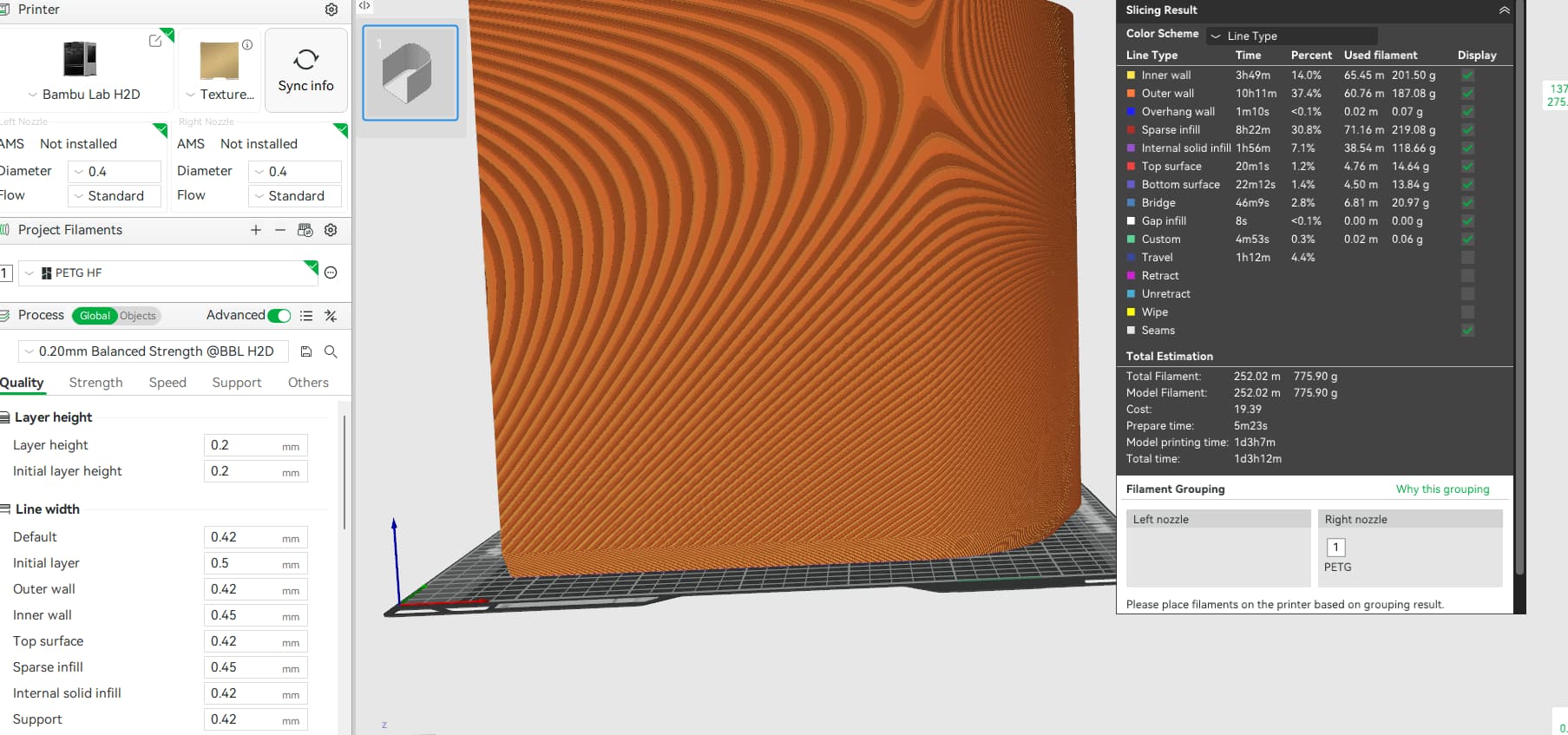
Unfortunately, full prints with Bambu PETG HF dried filament are terrible, nozzle 0.4 layer 0.2 Bambu profile for . While I can understand that height can affect quality, H2D is much more expensive, also due to the double bearings, which are designed to ensure the quality of high prints.

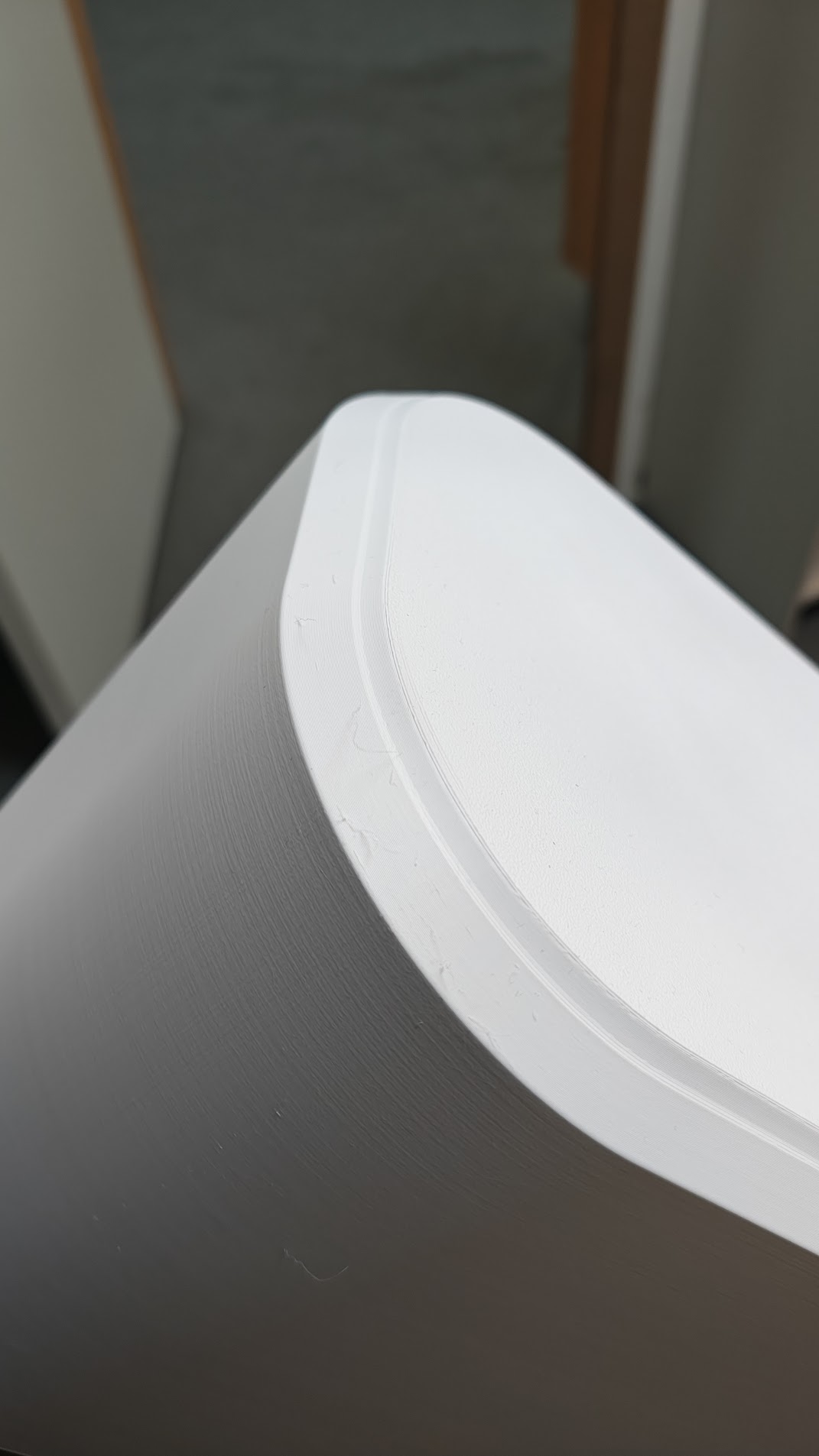
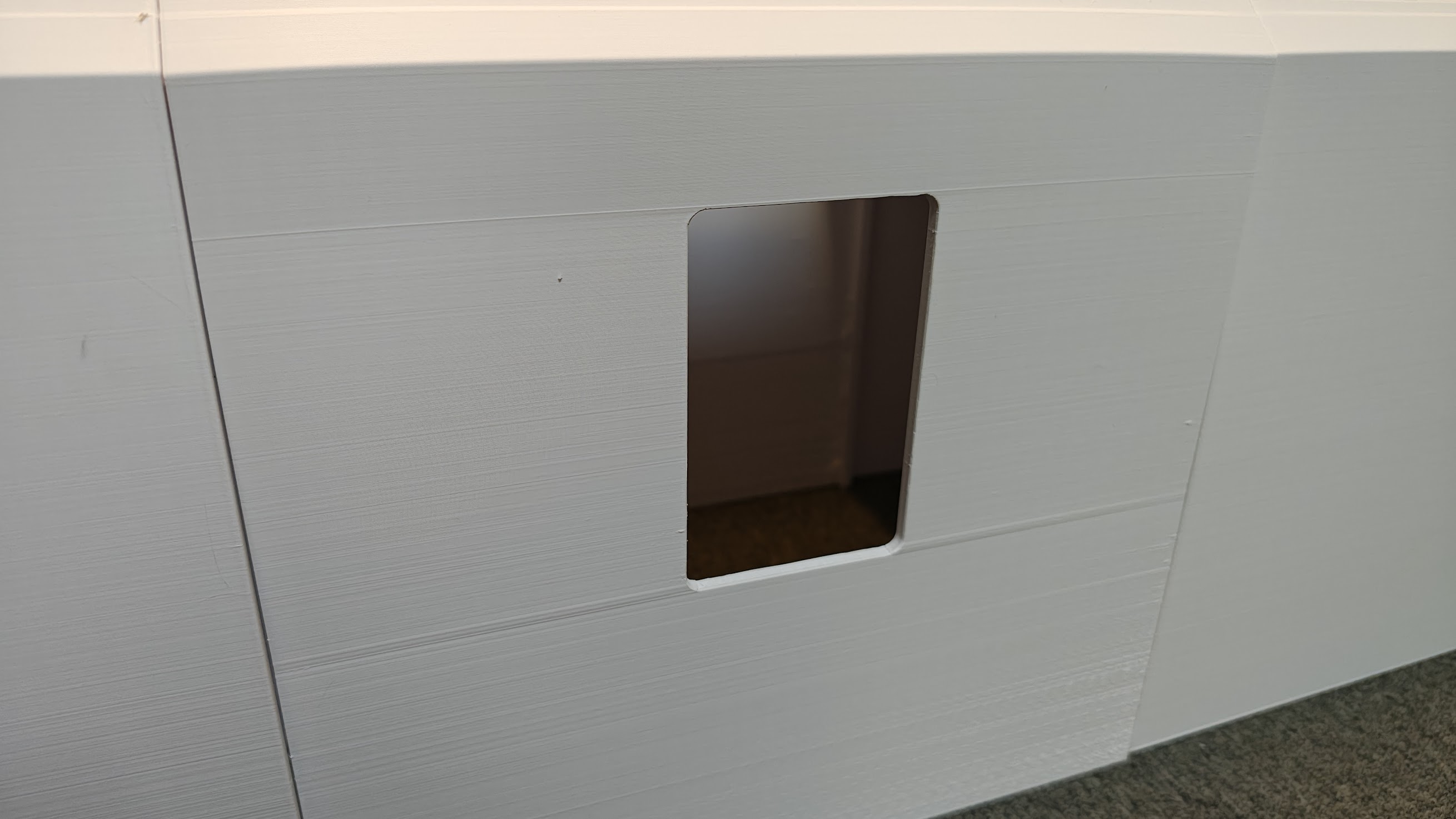
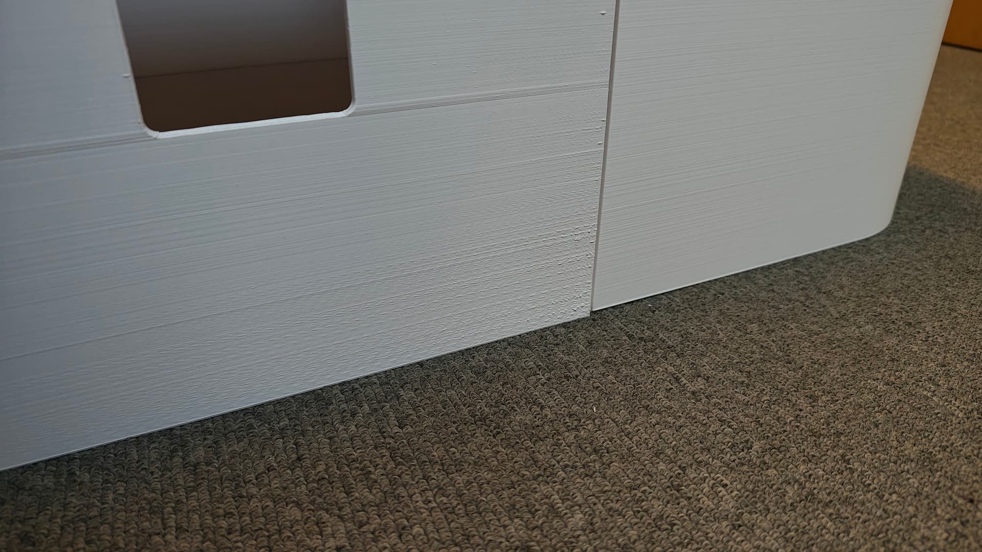
Here, the quality is nothing like a good printout.


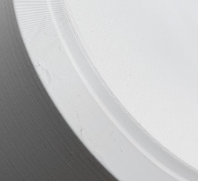
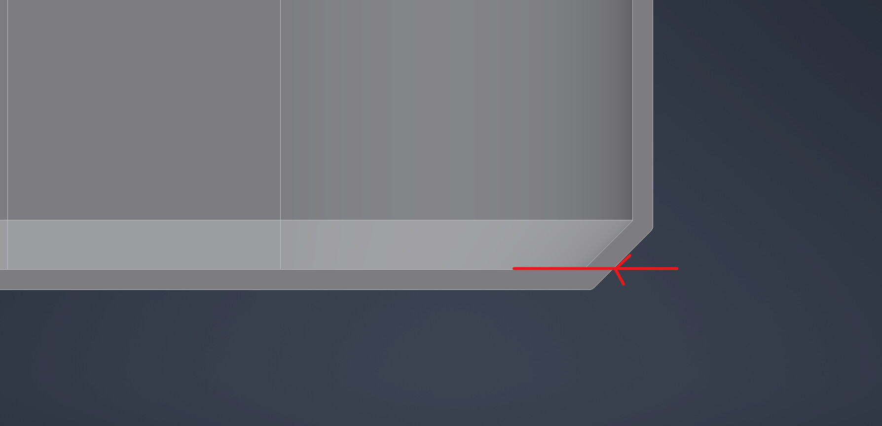
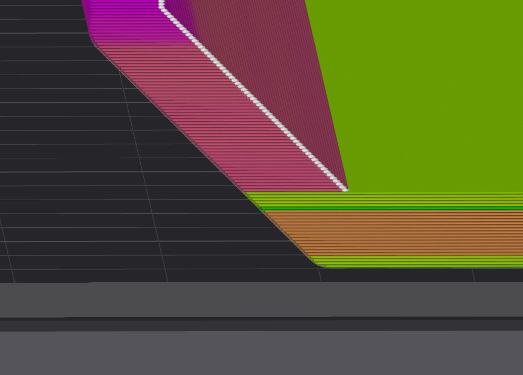
I used a 15 mm chamfer, so there shouldn’t be such a jump in the print, right?

Do you think I should create a ticket and report the machine?
Thanks in advance for any answer.

Default profiles are pretty bad. Run the filament through the calibrations and then slow it down a little bit.

That ridge at the bottom is pretty unavoidable for prints like this where there’s a large flat surface that transitions to walls only. It’s due to shrinkage. You can try to keep the chamber warmer to help it but it’ll never really fully go away. I’ve had the chamber temp as high as 45°c with PETG-hf.

3 Likes

I’m 99% sure it’s your model design’s problem+shrinkage, post your 3mf file here and I’ll point out the problem. Also how did you dry the filament?

2 Likes

Hi there. Completely new filament 8 hours / 60°. Tomorrow, as soon as I arrive at work, I will upload the 3mf file. Thank you for your help.

1 Like

PETG should be dried at 65C @ 8 Hrs, if you’re using AMS 2 for drying then it needs longer, preferrably 12Hrs. The main issue of this print comes from the model itself and also slicer settings, once you’ve uploaded the 3mf I can share how to correct it

2 Likes

I don’t know if I would call those prints “awful”. The model/settings could be tweeked for a slightly better result but there still are limitations with FDM.

1 Like

All in all, I was a user of Ultimaker and Prusa devices. I have been using Bambu for several weeks now. I have never seen such a print in a top-of-the-line machine before :slight_smile: Chamfer 15mm has never given such a result anywhere else.
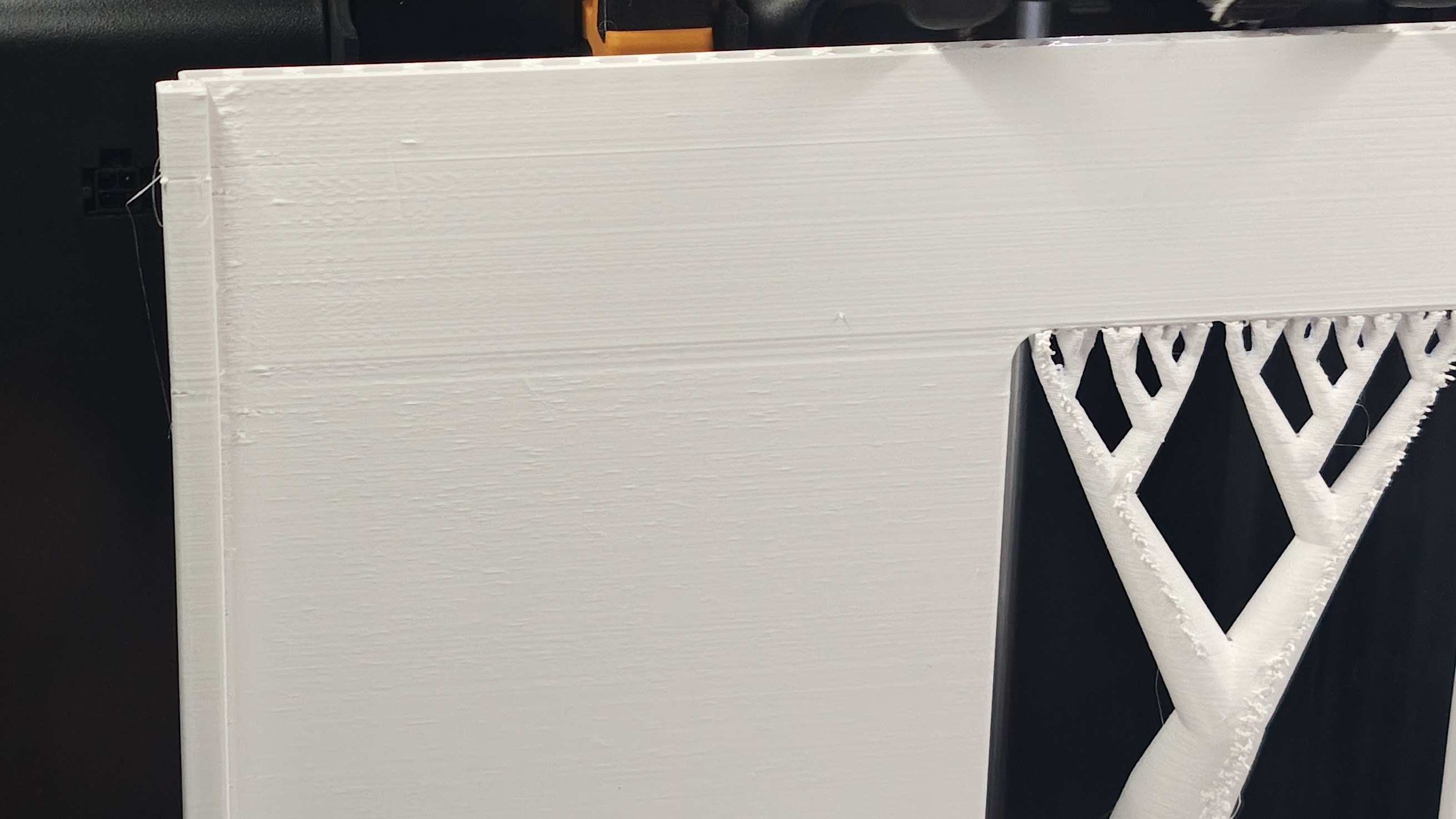
In this case, it would be understandable if the whole thing had some flaws, but here there is simply a jump. Any “windows” / holes in the printouts also correspond to lines around the entire object.
That’s why I call them awful :slight_smile:

2 Likes

The problems stem from speed and the FDM process. The faster you print the more of those problems show up.

For the chamfer, a simple change from 45 degrees to 48 degrees will make a big difference. Especially with some small fillets around the top egde.

4 Likes

Great. I wiil try this :slight_smile: Thanks!

1 Like

a few things that i’ve noticed already:

1. the filament is definitely still wet:


The uneven extrusion here is caused by either wet filament or bad Pressure Advance (Bambu calls it Flow Dynamics or K value)
2. you have bed adhesion issue; the part warped slightly near the corners.

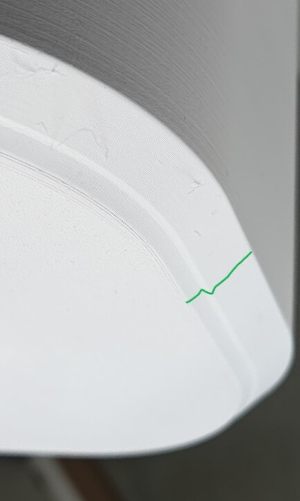
This kind of line is caused by warp. The part warps lifted, and that blocks normal extrusion, which causes this ugly line over extrusions. This warp is commonly caused by bridging layer under large flat surface. To prevent it, either slow down printing, or use glue, or both.

**3. Over 100% overhangs **


This is an over 100% overhang. There’s no fast printer can do this well enough. By over 100% I mean that at least one or two lines in the same layer has completely no support under it. So, it’s completely attached by inner walls in the same layer. And it won’t be printing well at all. And it would also introduce extra cooling due to slow downs and overhang extra cooling fans. So you would get weaker part, uglier part, and probably warped part.

2 Likes

If the part will fit in an X1C, get one of those. They will print out fine.

3 Likes

I believe you could try doing variable layer height just for that chamfer. lower it should allow more overhang. but i rarely use PETG

1 Like

Hi. Here is 3mf.

4x Side.gcode.3mf (4,5 MB)

Here is a print of same part, but I did cut just a piece to see if chamfer is ok.

Thanks in advance

No not the .gcode.3mf, but the raw 3mf with your model and settings

Thank you for your support.

  1. Of course, that’s how it looks. However, there are two issues. The filament was new and dried immediately before use, and the second important issue is that this problem only occurs in the print above a certain height. Before printing subsequent elements, I dry the filament again according to your earlier recommendations.

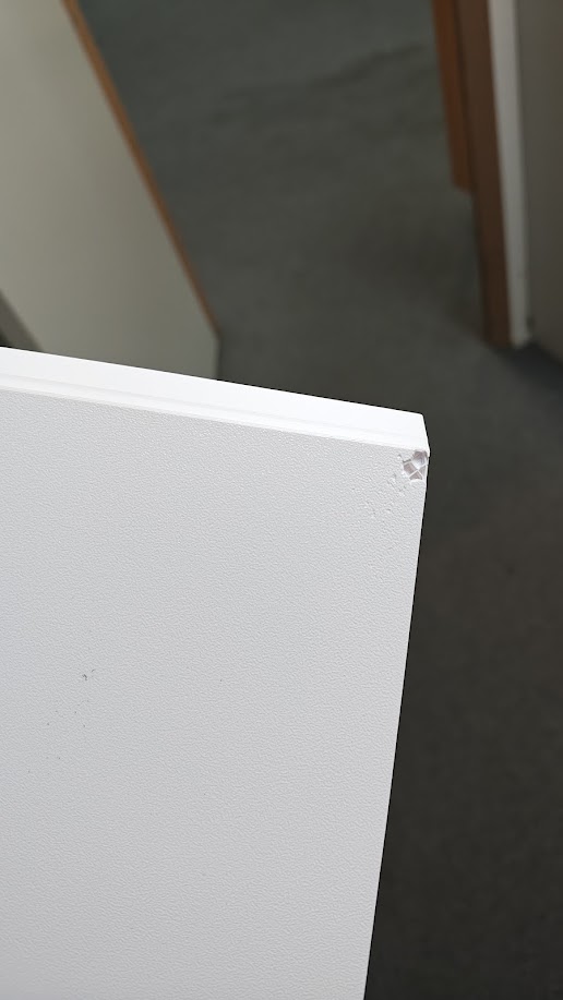
  2. I clean the print plate before each new print. Every print sticks like crazy (see photo below). This print also had supports enabled! That’s why I find it very surprising.

  3. There should be no overhangs here. The slicer also did not show any overhangs.


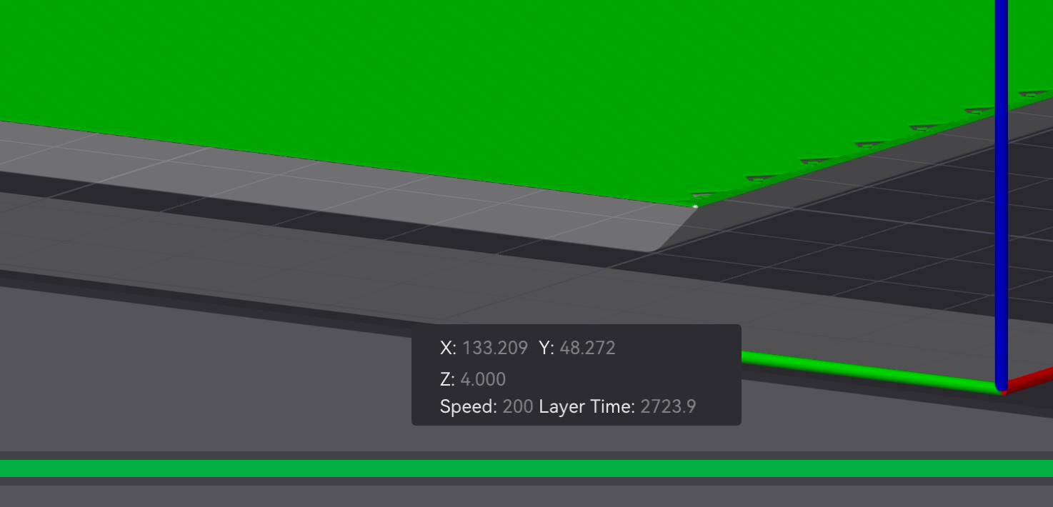
    This change in line when printing is equal to the height of the base. Doesn’t that mean something?

But I understand that using the Bambu profile for Bambu filament was not a good solution. :slight_smile:

Really, thank you so much for your help. They said that if I switched to Bambu, it would be impossible to get help. It’s great that they were wrong. :grin:

Sorry :slight_smile:
Here is a project, I hope that’s what you meant.

4x Skærm ben-print 2026 .3mf (115,8 KB)

and step if it will help
4x Skærm ben-print 2026 .stp.3mf (45,0 KB)

Yep. It’s caused by strong shrinkage. The pulling force in the corners are super huge

2 Likes

First of all, I wanna reinstate the importance of understanding shrinkage, and shrinkage differences, for FDM.

Shrinkage exists and it’s very powerful, it’s a curse among all current FDM machines. And the difference of shrinkage between each layer, is often the culprit of most of our problems. Believe me or not, it’s also why there’s no point of bragging how fast a FDM printer can print, because shrinkage would ruin it all.

So remember shrinkage, and shrinkage differences, because they would haunt us a lot :confused:


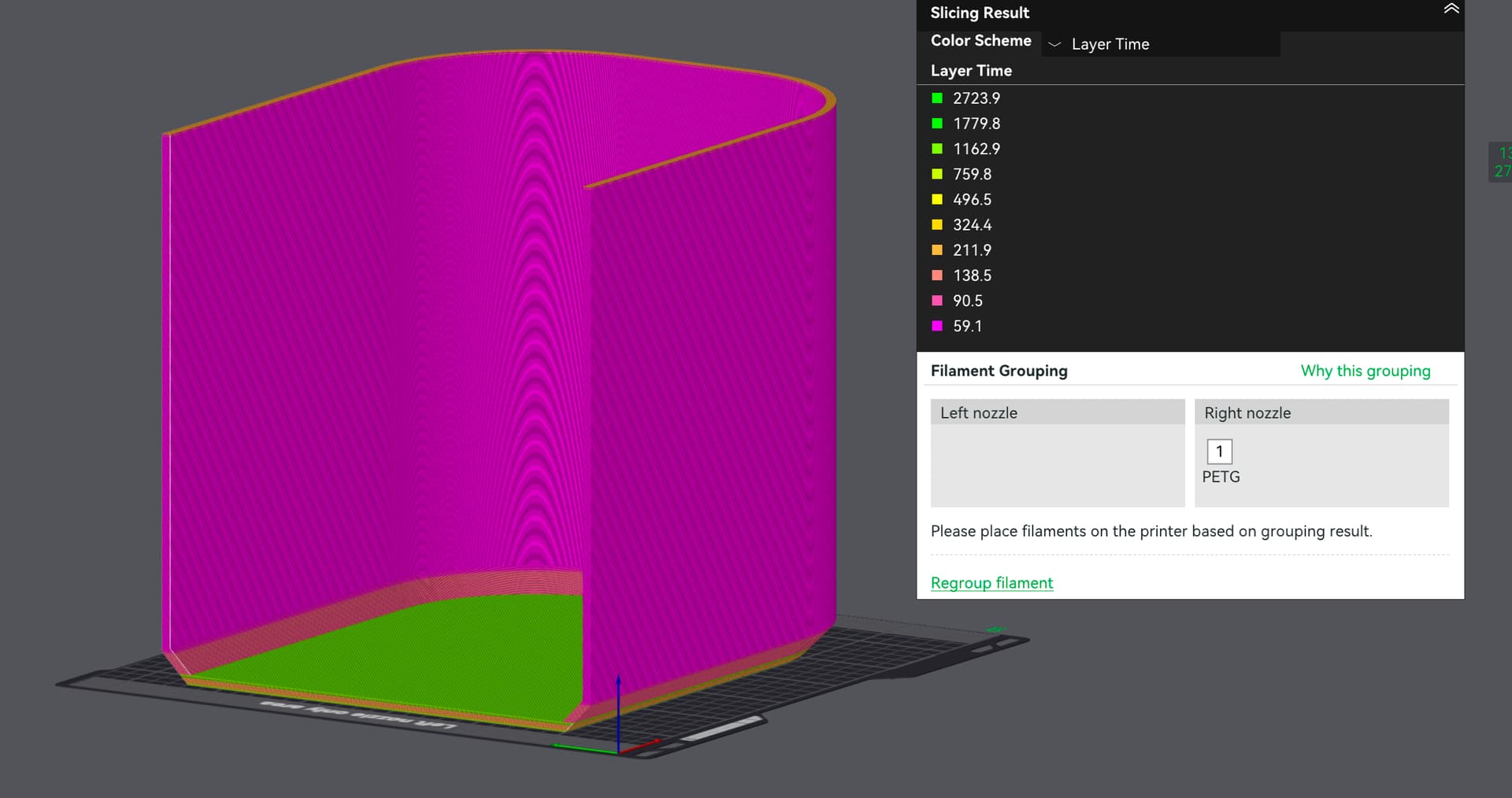
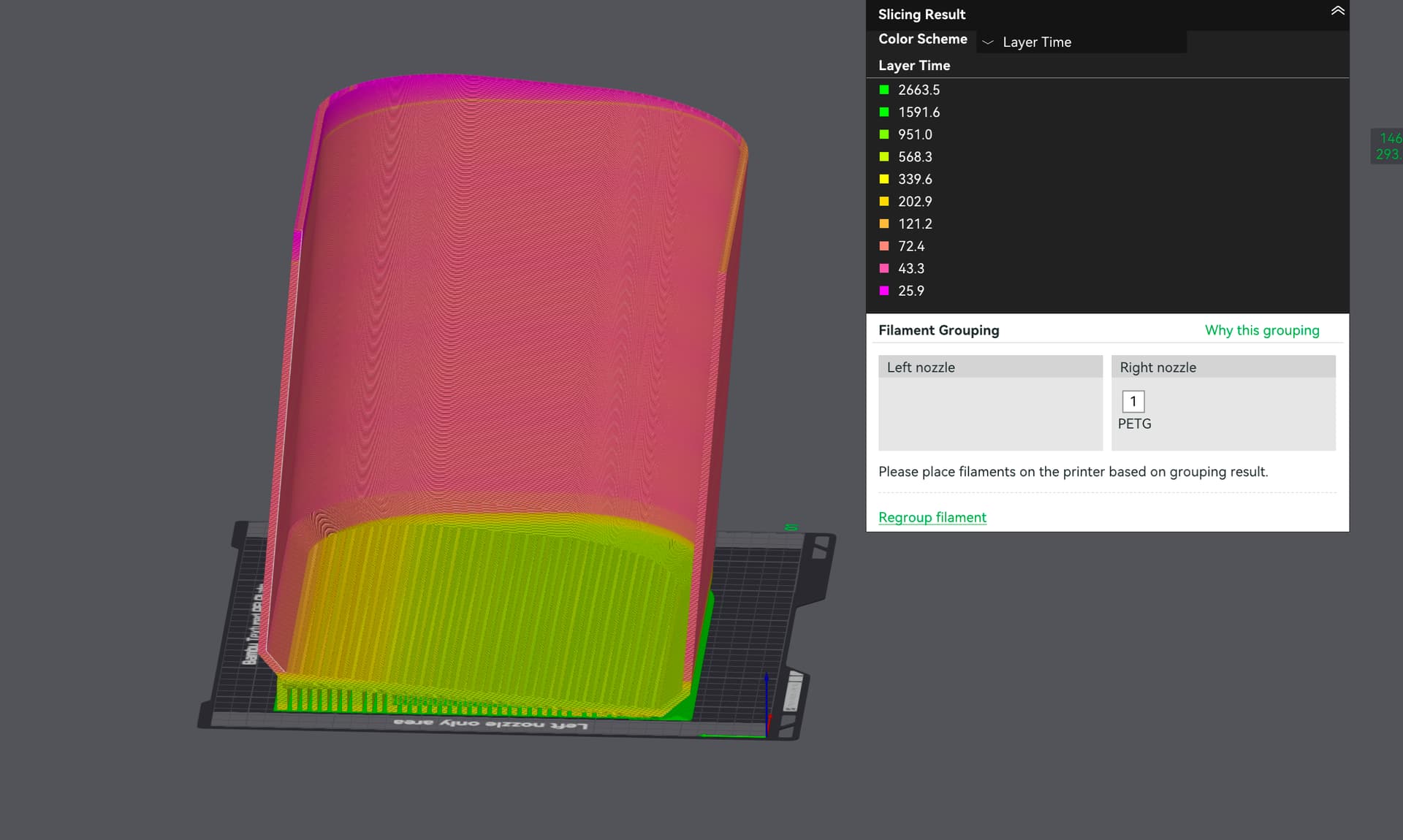
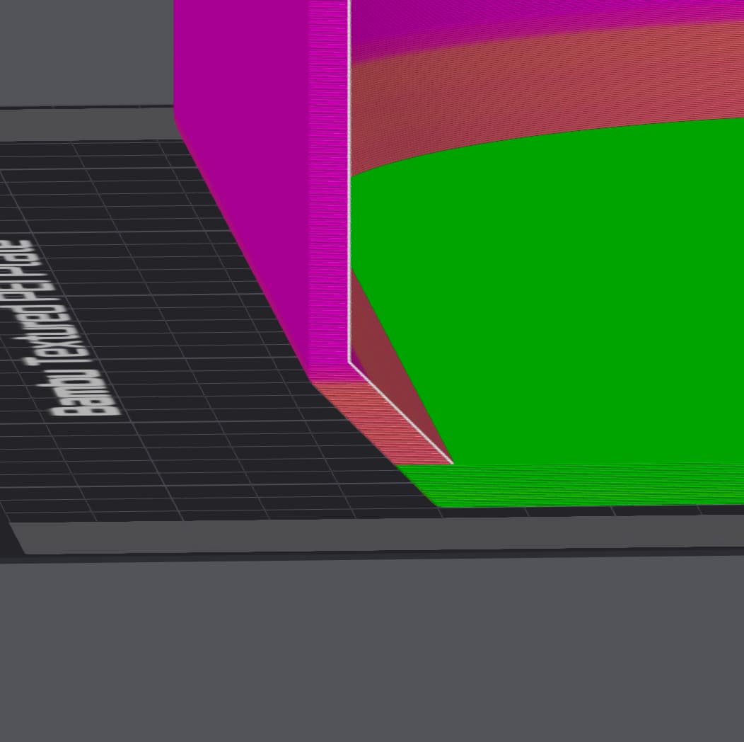
So starting from layer time view. You can see that the top surface layers are taking exceptionally long time to print.

The Internal Bridging Layer took a whooping 2800s to print, which is why it’s shrinking so much compared to other layers. The layers below the bridging layers only takes 190s to print. That’s more than 10 times of time difference alone. Then, it’s also blowing fan speed to 100%. The normal petg printing fan speed is 20%. So youre getting a huge ton of cooling from both high fan speed, and extra layer time, and extra layer time * extra fan speed. This alone causes massive shrinkage difference and can pull the corners upwards.

Now, another issue is that there’re too many straight corners.

FDM doesn’t like straight 90 degree corners. On the XY plane, if you can, always use a fillet.


Straight sharp corner = huge pulling force from shrinkage
Fillet round corner = much less pulling force
A huge pulling force can 100% lift the straight corners, or cause deformations, even if it doesn’t seem like it. Sometimes it can even break your model or printer. So avoid it at all cost.

Remember that you’re printing PETG. PETG is a high shrinkage material. And never underestimate the power of shrinkage, it can lift your corners, it can separate your model’s layers (yes it happens, literally breaking your model due to shrinkage alone while printing), it can lift up the build plate, it can break glass plates, it can destroy early printer beds…

Always take shrinkage into consideration when doing designs unless you’re exclusively using carbon fibre or glass fibre filaments. They have exceptionally low shrinkage rates.

Things that might help with shrinkage:
At the cost of overhang/bridging quality:

  • raise chamber temp
  • raise bed temp
  • reduce cooling

At the cost of money and details allowed:

  • Carbon / Glass fibre filaments

At the cost of part strength and printing time:

  • Print slowly like old 3d printers.

At the cost of extra design:

  • Fillets for all corners in XY plane, avoid all sharp corners. My personal guideline is at least 4mm radius of fillets if possible.
  • Print in different angles with supports to prevent large flat surface issue.

    E.g., a slight rotation spreads out the bottom surface into multiple layers. Each layer now has a much more uniform layer time and it won’t cause as much issues. Bottom surface layers are now using 350-600s each layer to print and that’s much better than from 190 to 2800

However I do wanna say that in the special case of your model, another way to reduce the issue is to just print a thick bottom surface.
This is your original settings’ layer time view:


The main culprit here is that bright green bridging layer. It’s taking 2800s compared to previous layers’ 180s. As long as you can smooth this out, you would get a much better result.

So a slow layer above a fast layer is big no no. But a fast layer above a slow layer is fine.

Using this logic,
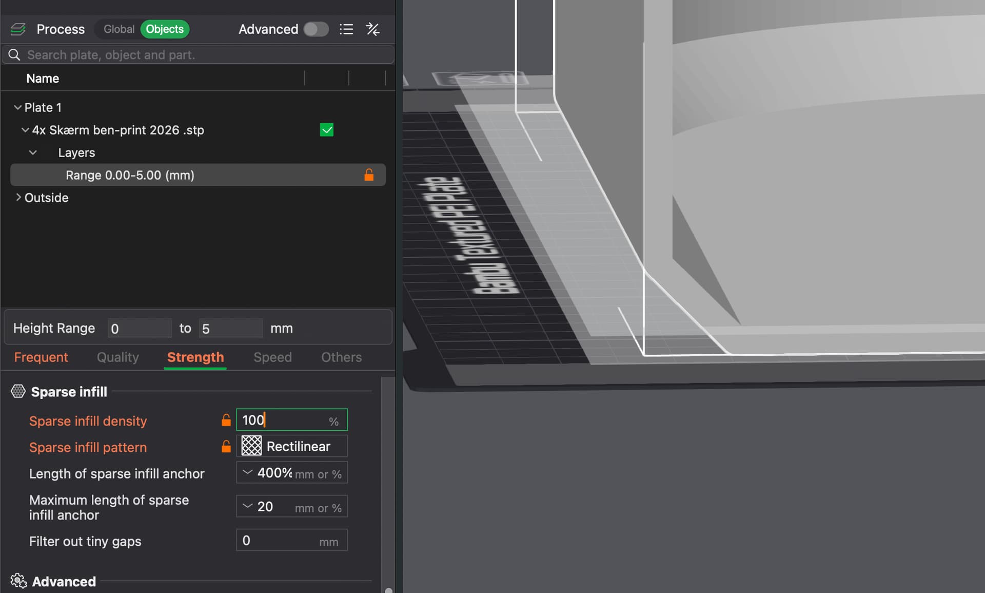
Instead of using default settings, for this one particular model, if you print the entire bottom at 100% infill, by using modifiers, you can set it like this:

Then you would get a layer time view like this:

The rule of thumb is:
Slower layer on top of faster layer = bad results. E.g., 2800s on top of 180s = bad
Fast layer on top of slower layer = usually not very visible E.g., 180s on top of 2800s = nothing serious

Okay now I really need to go to sleep.

8 Likes

Amazing! I’m starting my journey with Bambu Lab and already see, that community support is something big :grin: I will try all you suggested! I really appreciate all your help Master! Thanks :pray:t2:

Thank you for that! I never explored to know about time view or why it’s important. Makes sense and will be very useful.

1 Like