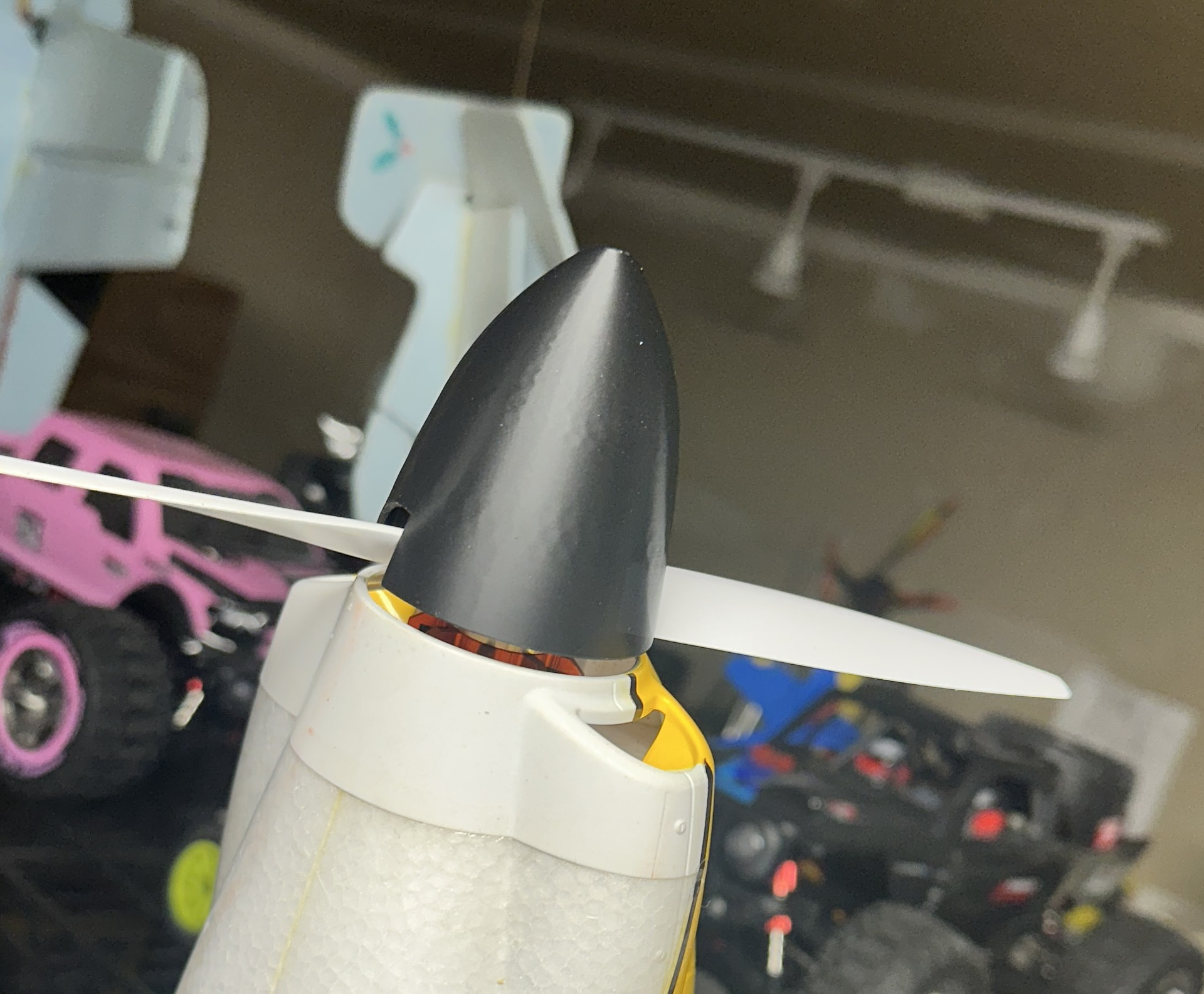
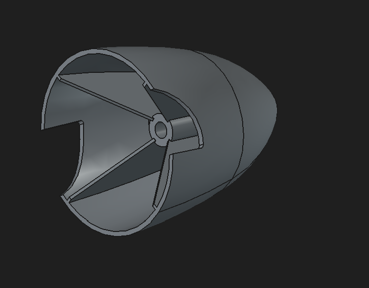
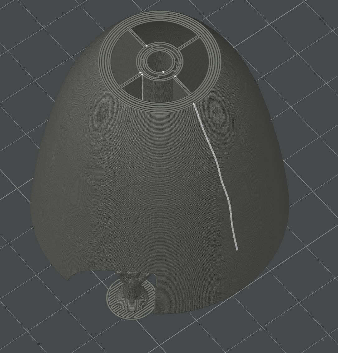
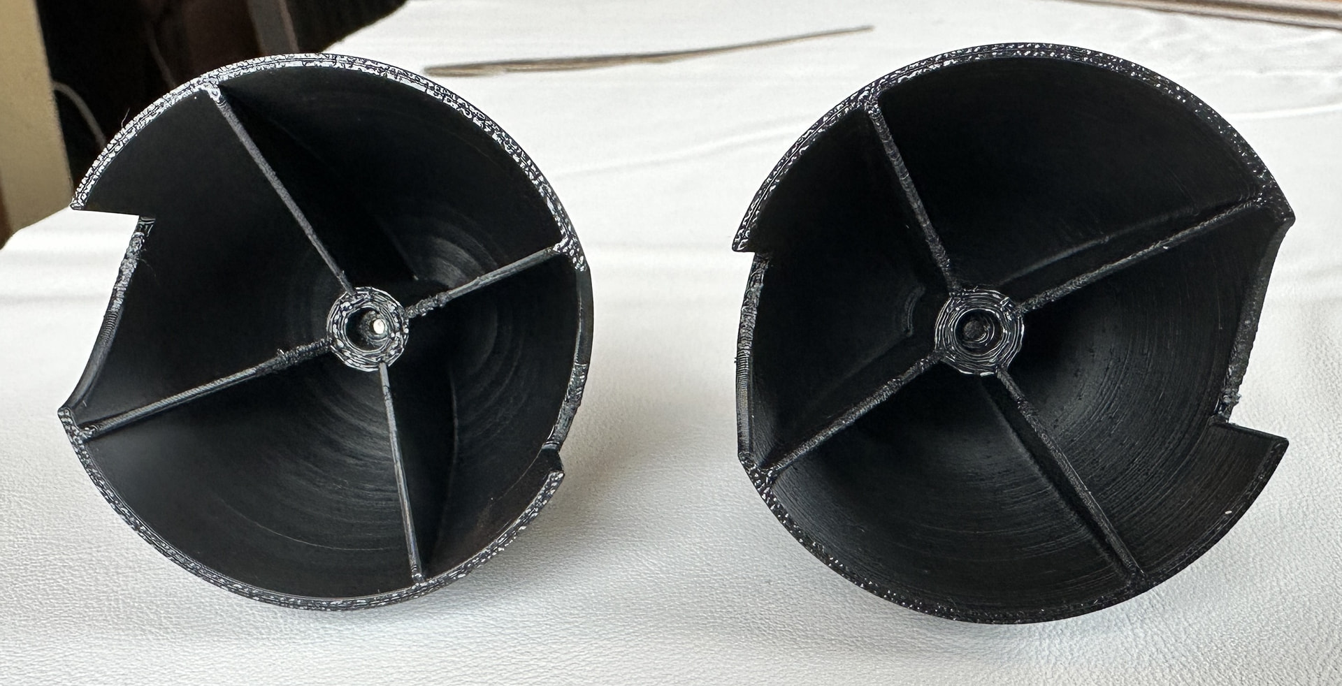
I designed a replacement spinner (in FreeCAD 1.1) for my 1.1m wingspan Sportix RC plane. I designed it with a 1.5mm outer wall thickness and the 4 inner supporting vanes are only 1mm thick. I printed it on my P2S using Bambu PLA Tough+ and the setting in Bambu Studio is *0.16mm High Quality @BBL P2S with tree supports. All other settings are defaults with 15% Gyroid infill. If you look at my picture of the printed part, you’ll see a sort of blobbyness to the surface that has a hexagonal look to it. There’s also a line down one side which is also shown in the slicer view.
I have been researching vase mode but I’m looking for advice to maximize strength while getting smooth outside surface looks. In theory, this could spin as fast as 16,000 rpm
To post pictures, you first need to get familiar with the forum: Read a few threads, spend some time here - it won’t take more than 15 minutes. This is to prevent bots from spamming the forum.
If I’m not mistaken, you should be able to do that by now.
Takes a few posts to be able to add attachments to keep malicious stuff at bay. You’ll be able to post a photo pretty quick I think. There are things like time spent reading threads and text posts that get you there.
About the spinner, the line you see is a seam. They are needed where extrusion starts and stops on a layer and there are a number of ways to minimize them. Look for threads here or the Bambu wiki about seams.
About the vase mode, I wouldn’t recommend it. It’s only a single wall/shell so isn’t very strong. Depending on the model, the spinner can see high stresses especially at high RPM like 16,000RPM. I’d go with more walls to get a more solid model with less infill (which may be the source of the texture showing through?)
It’s certainly something to be careful with and test at sustained high RPM. You don’t want it coming apart and throwing plastic shards. I’d expect printed parts to almost explode if they were to fail and come apart. I’d wear safety glasses for all testing until you know it can take the stresses.
What program are you using for design? I can’t tell from the spinner image if that is infill patterning or how fine of a mesh you are outputting.
In Fusion at least when exporting an stl file you can adjust the “refinement” slider/number which is basically just how fine a mesh it uses to keep the ideal/true surface and actual surface within the specified error.
Or, if you show an image in Studio from the preview pane showing a layer at the height where you are getting that patterning it would be obvious if infill or not. You can also just change the order of printing infill vs walls and maybe clean that up (if it’s infill).
Strength-wise it’s looking pretty good and on an electric motor you won’t get compression pulses using an electric starter. I can’t say it’s ok and safe but I personally would use that (with appropriate precautions).
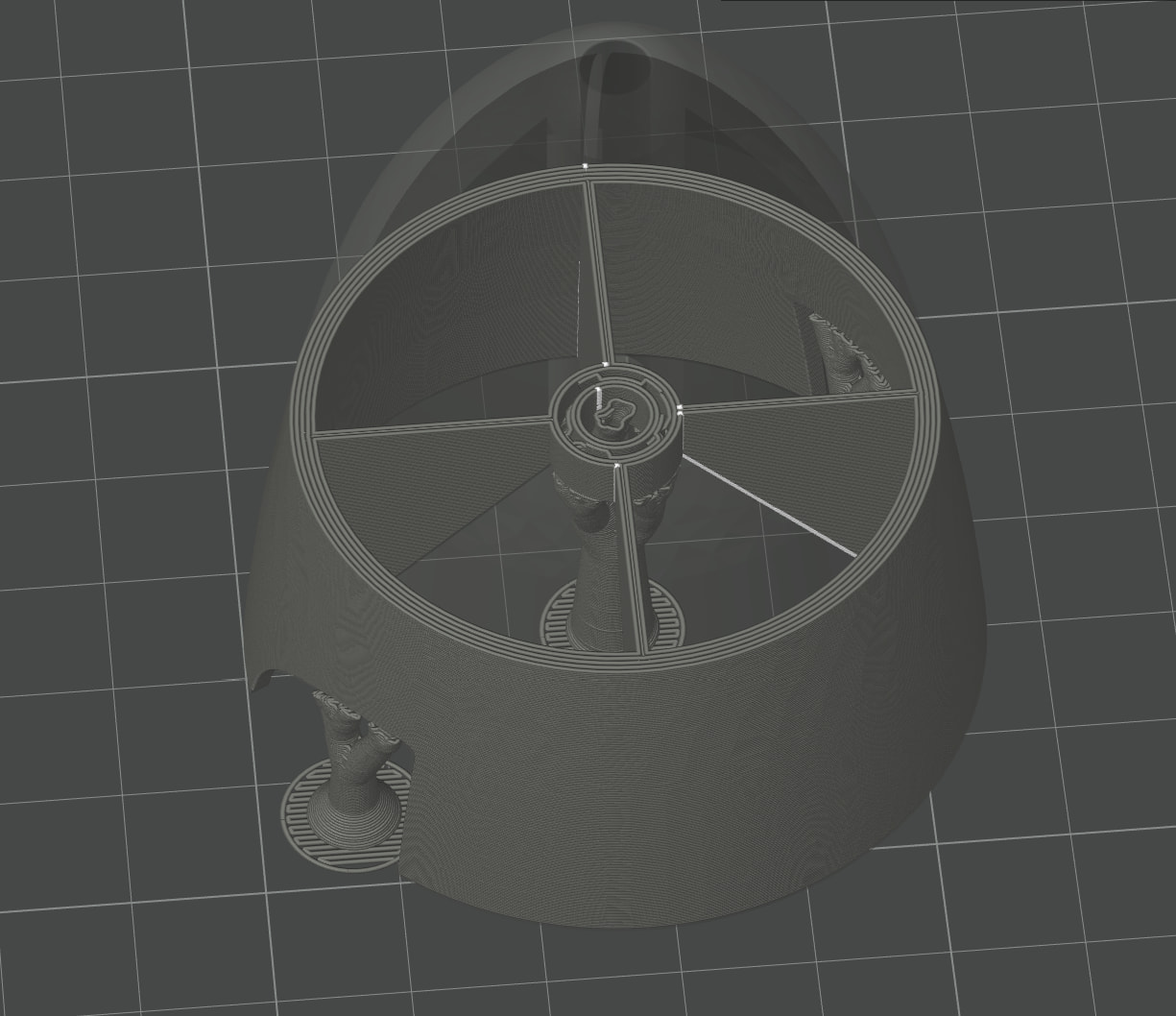
I’m using FreeCAD 1.1 and there seem to be no options on Export to STL. I’ve included a picture from the slicer around where the marks are on my print but there doesn’t seem to be a recognizable infill pattern, it just looks like circles of filament. In Bambu Studio, the wall loops are set to the default 2.
I guess order of infill/walls doesn’t matter if there’s no infill.
Any chance there is a precision or fineness setting that might be the same thing? In Fusion the option to make it smoother is in the popup menu when you export an stl but maybe you have a setting somewhere else?
At least when exporting stl files in Fusion I can get totally rid of that visible faceting by setting a small error. Hopefully it’s there somewhere because it makes a noticeable difference.
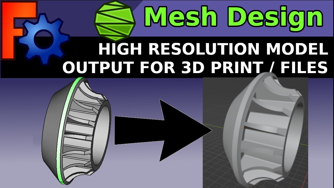
Well, in short, no. But that was because that setting is only for the display in FreeCAD. What I found was that you have to follow the steps in this video…
Which means that you change to the Mesh workbench, Create a Mesh from Shape and use the settings in this step to select accuracy, and then export the Mesh from Shape part to STL. I chose the NetGen > VeryFine option and the resulting STL file was 10 times bigger and obviously much finer detail. It’s just starting the print now but the preview in Studio no longer shows the tessellations so, hopefully, I will solve my issues.
Before this enhanced export to STL, I also added some fillets to my part and used random seam position in the slicer.
No problem at all. Used to fly R/C so took special interest and glad you got it sorted. But yep, smaller triangles to make the surface smoother will blow up a model. Go superfine and they can get pretty big.
The random seam locations will cause little bumps on the print. There’s ways to minimize them but seams are unfortunately a required thing. But you can minimize them through settings. Look around for topics on minimizing seams and you’ll find the tricks.
Something else to keep an eye out for since you are looking for extra quality is hard transitions in a model can leave artifacts on the outer surface due to changes in layer times. Looking at how you have those spiders from the center hub reach from back surface to nose you may not see any issues, though.
Where they appear is going from for example a backplate to the shell of a spinner (if it was all one piece), the backplate would take a while as a solid circle but the spinner itself on the next layer up would be relatively fast. Internal chamfers or fillets can be used to make the layer time transition more gradual and minimize surface artifacts - if they are even an issue.
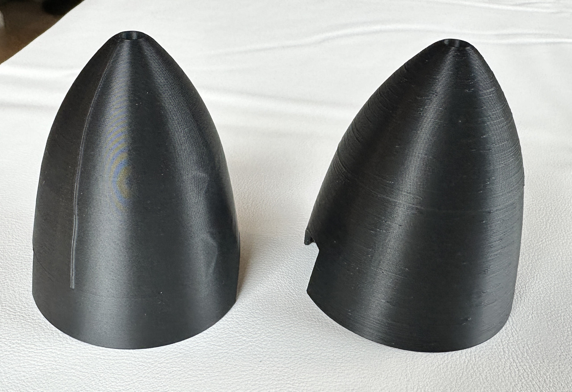
Here’s some pictures with the original one on the left and the higher Def one on the right. The lumps and seam line are gone on the Hi Def one but there’s bumps where the random seam has been scattered but, all in all, the Hi Def one is much better IMHO.