How much inaccuracy is introduced by slicer? A lot! [recent studies]

The following is based entirely on information from ‘I Built a Thing’, which I am passing on here. Therefore, if the text contains the words ‘I’ or ‘we’, this does not refer to me; rather, it was written by the author of the studies.

Authors: Michel Beyer, Alexandru Burde, Andreas E. Roser, Maximiliane Beyer, Sead Abazi, Florian M. Thieringer


Have you ever spent hours calibrating your printer, only to print a real part and find that the dimensional errors are still there?

Most of us blame the printer, the filament, cooling, shrinkage, belt tension, or thermal expansion. But what if a significant part of the error is already present before the printer even starts moving?
In this video we investigate one of the least discussed sources of inaccuracy in FDM 3D printing:

  • the slicer itself

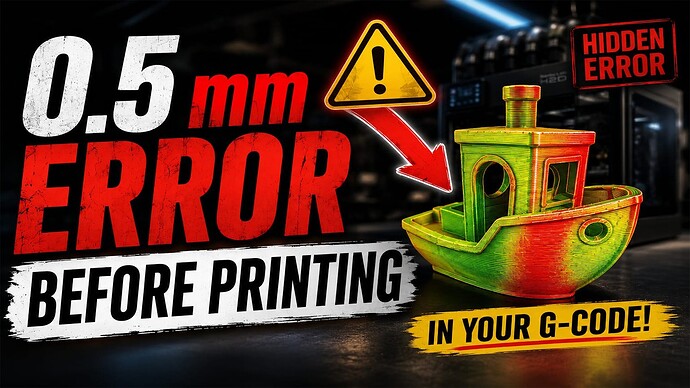
Together with my co-authors, I published a real peer-reviewed scientific paper investigating how different slicers alter geometry during the conversion from STL to G-code. We developed a slicer-independent framework that reconstructs geometry directly from G-code and compares it to the original model in order to measure how much error is introduced during slicing alone. The results were surprising: depending on the slicer, geometric deviations approaching 0.1 mm can already be introduced before any filament is extruded.

But we didn’t stop there. We physically printed the models, 3D scanned them, and compared the scans back to the original STL files. This allowed us to estimate how much of the final dimensional error comes from the slicer and how much comes from the actual printing process. The result challenges some common assumptions about 3D printing accuracy and raises an important question:

  • If the slicer already changes the geometry, how much of the remaining error is really the printer’s fault?

This study investigated the geometric and volumetric accuracy of G-code generated by five commonly used slicing software packages: PrusaSlicer, Cura, Simplify3D, Slic3r, and Fusion. The comparison was made between reconstructed models derived from the G-code and the original STL files.

A custom Python-based pipeline was developed to extract point clouds from the G-code, apply geometric corrections, and compare them with the reference meshes. This allowed for precise assessment of slicing-induced deviations independently of printer hardware. The discussion below addresses the validity of the registration method, the repeatability of slicing outputs, the accuracy of the slicers across multiple models, and the implications for clinical use and process validation.

Read the paper here for free: https://www.mdpi.com/2313-433X/12/1/25


Personal comment from me (RetroSharky): In short, the slicer is less accurate than we might think. While it works perfectly with calibration cubes, it produces quite a few tolerance errors with complex objects - errors that can’t even be fixed by calibrating the printer. The errors are caused by the software.

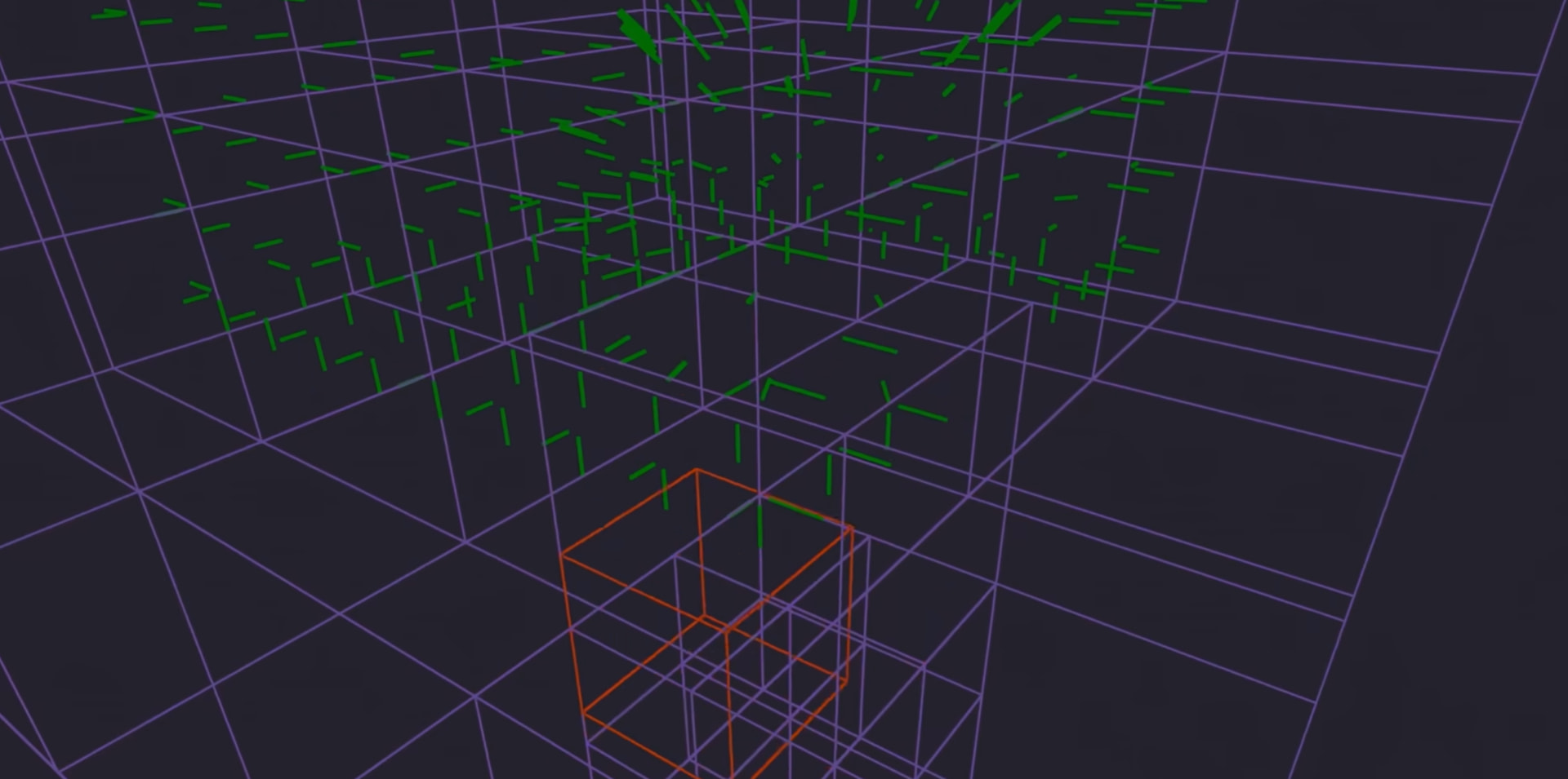
It’s also interesting that some slicers are more accurate, while others perform less well. Researchers have now precisely measured just how inaccurate slicers are. Fusion, right side, most inaccuracy


2 Likes

The biggest problem is not the printer or slicer but model designers who don’t take under consideration what 3d printer can and can’t do, also how the g-code is generated based on shape.

We physically printed the models, 3D scanned them, and compared the scans back to the original STL files. This allowed us to estimate how much of the final dimensional error comes from the slicer and how much comes from the actual printing process.

This is not science, this is nonsesne.

Did you even watch the video?


First, they scanned the g-code virtually to determine the amount of deviation caused by the g-code / slicer alone. To achieve this, they developed a highly precise program that did not previously exist. This eliminated all external factors, such as printing itself and filament. Even then, significant inaccuracy were observed by slicer.

This measurement was proof enough; there was no printer involved at all - it was purely a software / g-code / slicer analysis:


What you described was the second step: scanning the 3D model using high-precision equipment and comparing it with the STL file from the first step. However, the proof had already been provided with the first step. The second step was merely a comparison of the results. This served as an example of what happens when all the errors add up - including those from the printer, the filament, and so on.


You really have to watch the video; otherwise, of course you’re going to think it’s nonsense if you don’t understand what it’s about.

Did you realize that you don’t have to print anything at all to measure the slicer’s inaccuracy - thanks to the researchers?


By the way, I wouldn’t call a 0.5 mm inaccuracy “nonsense” if it’s just coming from the slicer; overall, it adds up - the larger the object, the more it adds up.

Which scanner did you use and how was it professionally calibrated, most scanners will add their own amount of variance from the base model, its why you can quite easily spot raw scans of things as they show more imperfections than are actually present on the model itself

So there will always be some amount of variance that isn’t down to the printer or the gcode

So, honestly: I’m now strictly ignoring all comments that mention the scanner and haven’t understood that this was only the second step, and that the proof was in the first step.

This is the section where the G-code was scanned virtually. No printing is involved in the first step. The video starts exactly at this point - timestamp.

1 Like

The paper doesn’t mention perimeter generator used, while we do know that classic vs arachne produce different results.

As for arachne - there were some changes recently to orca:

2 Likes

Good point! Maybe we can get in touch with the researchers somehow and bring this to their attention. I’ll see if I can get in touch with them. I’ll phrase it as a question. But I’ll have to look that up first. There were several researchers involved, and I have no idea who has whose contact information. :+1:

What I’m calling nonsense is comparing apples to apples.

First, we need to realize what G-code was made to do, how it works, and for what types of objects and tool sizes it was designed.

In a nutshell, G-code was developed to control CNC machines in XYZ coordinates. Some geometric shapes are not possible to achieve exactly, so compromises need to be made depending on the machine, nozzle, material, etc.

Different implementations use different compromises for certain shapes, nozzles, and printers, hence the deviations.

Different shapes will produce different deviations on different printers.

This is, in my opinion, dishonest science for the sake of being published.

If you know how those compromises are achieved, it is easy to pick an object that will show the superiority of your solution over others, but with a different shape, the results could be totally different.

1 Like

They have gone through all the trouble and didn’t realize this simple fact? That’s why I call it dishonest science. Those dudes published this because they wanted to have some work published for whatever reason, not for the sake of “science.” Classic vs. Arachne is only one aspect; there are way more.

Slicers are not the same. They do slice differently, and for some shapes the G-code will look different from others. It might be more accurate for shape A, but less accurate for shape B. Measuring this is not possible in a way that is fair to all shapes. But it doesn’t mean Slicer C is better than D, because on a different shape it could be totally different. One would have to look under the hood of each implementation and see how they go about the earlier-mentioned compromises.

You don’t get it, do you? No printer was used at all. For the initial measurement, only the slicer was used. The type of printer doesn’t matter at all. Instead of watching the video, you’re just double-down now.

I’m seriously starting to lose faith in your attention span.

That’s exactly what they did - saw under the hood of the slicer. Come on, what’s wrong with you? Why don’t you take a look at the video or the paper, please? This is just completely ridiculous.

So what’s your intention here? To derail the discussion without even having read the paper? Without having watched the video?

You don’t get it. Slicers and their implementations and workarounds are made with particular printers in mind. That’s why deviations will be visible from the G-code view.

I’m not wasting time on pseudoscience. What they claim in the title can’t be honestly measured for all shapes. Those variations will change based on shape, and each slicer will produce different G-code, but we can’t say this slicer produces more accurate G-code. We can, but we need to say for shape A, because for shape B another slicer could be more accurate.

2 Likes

Dude, seriously - that just proves once and for all that you haven’t even watched the video! That’s exactly what they’re describing: that the calibration cube always came out perfect, but the bigger and more complex the object got, the less accurate the slicer became. Please get a grip.

I want to discuss this seriously and provide value to the community, because these results could be very important if you want to print highly precise parts, and all you’re doing is causing chaos in this thread.

For example, that someone uses a slicer that isn’t so inaccurate for highly precise parts.


An interesting discussion would be, for example, what the point is of printing calibration cubes if they aren’t representative of complex objects at all.

1 Like

I didn’t watch the video, and I will not. You almost got it. You can’t pick “the best slicer” because each slicer will be the best for a particular shape, so claiming that one slicer is the most accurate is misleading to this community.

Depending on the shape you are printing, a different slicer may produce better results. Also, many slicers and their implementations are developed with specific printers in mind, and various workarounds for G-code generation are used based on the characteristics of those printers. Because of that, comparing one slicer’s G-code to another slicer’s G-code on some random shape is misleading.

Do not mislead the community. If you truly want to cover all shapes and all scenarios, let users choose the slicers provided by each manufacturer. The probability of achieving the most accurate result across the full range of shapes will increase significantly.

This shows you have no clue how and why slicers generate code one way or another.

What’s old is new again

Isn’t this kind of the same revelation as cura was trying to address when they added Slicing Tolerance modes? Applies a strategy to edge boundary definitions

Okay, that says it all… I’m just quoting you as proof so everyone can see that you’re only here to disrupt the thread.

I post something that specifically refers to a research paper, and you don’t even read it to see what the topic is about and you think you’re smarter than all those scientists: Michel Beyer, Alexandru Burde, Andreas E. Roser, Maximiliane Beyer, Sead Abazi, Florian M. Thieringer

star-trek-patrick-stewart

1 Like

Unfortunately, it doesn’t explain how the measurement or calculation was performed. It seems to me to be a mathematical estimate? Does anyone know how it was measured? I can’t find any information about it. I’d really like to know.

As far as I know, no one has ever measured it with such precision as the research team did. This is because there wasn’t any software available that could measure it; they had to program it themselves.


Edit: or how they describe it.

This study investigated the geometric and volumetric accuracy of G-code generated by five commonly used slicing software packages: PrusaSlicer, Cura, Simplify3D, Slic3r, and Fusion. The comparison was made between reconstructed models derived from the G-code and the original STL files.

A custom Python-based pipeline was developed to extract point clouds from the G-code, apply geometric corrections, and compare them with the reference meshes. This allowed for precise assessment of slicing-induced deviations independently of printer hardware. The discussion below addresses the validity of the registration method, the repeatability of slicing outputs, the accuracy of the slicers across multiple models, and the implications for clinical use and process validation.


This also explains quite well why no printer was used in the first step, in order to rule out factors such as filament and shrinkage.

The lack of perfect accuracy does not surprise me in the least. An STL uses smooth lines and curves whereas g-code stair steps from layer to layer and steps its way around a curve. When designing for milling machines, the rule of thumb is that accuracy of fine detail is half the cutting tool’s diameter. If applied to to 3D printers, that would imply that fine detail can only be accurately reproduced to about 0.2mm in the X-Y directions, assuming a 0.4mm nozzle. Thus, with a 0.2mm layer height, if an object was created strictly adhering to a 0.2mm grid with no curves, the slicer and the resultant print should accurately reproduce that. Yet, falling outside that grid, accuracy is diminished.

I agree with the sentiment

The engineering principle that all good designers abide by is to design to the manufacturing processes. Reading forums like this one, I often get the idea that biggest problem most people have when 3D printing, is when trying to print objects that weren’t properly designed for 3D printing. It is one of the primary reasons why scanned and AI objects tend to print poorly.

I did watch the video. I think the creator muffed the landing with the 3d scanning he did of the finished part. Certain people (cough) will use that to discredit all the factual scientific work that the team did to publish their paper. Don’t get me wrong, I agree that the high resolution scan of a 3d printed mandible was more an exercise in curiousity than the pinnacle of scientific excellence, but it doesn’t invalidate the rest of it.

Yes, my thoughts exactly. Curves aren’t true curves in terms of machining. It’s a complex dance of stepper motors working together to draw miniscule straight lines that make a circle. One can imagine that this alone would account for the inaccuracies. I don’t mean that the printer itself is doing it, it’s working off the instructions from the gcode which did the translation to begin with.

Agreed. At least anecdotally agreed. Straight line tolerances/offsets = easy. Curves/weird shapes = let’s throw a dart to see which offset it lands on this time. I can use anywhere from 0.0-0.2 mm, in 0.01 mm increments. It’s maddening. It’s almost as if I should make bigger models….Nah.

I’ve mainly chalked up the tolerance discrepancy to everything after “slicing error.”

But I always suspected that there’s more to it than the 6 usual suspects. Going from a computationally generated screen render to a part that you hold in your hand means the first step - translating that model to machine speak (gcode) - isn’t so straight-forward. Meshes speak 3 dimensionally and have the benefit of producing curved shapes as smooth as your graphics card can render it. Printers speak line-plotter-y which is an entirely different thing. Yes, that’s a scientific word now.

1 Like

It would probably have been better if he had split the video into two: one part for the scientific section, and another for the scanning part which later served as a comparison. On the other hand, there will always be people who complain. Even in this thread, the criticism started right away, despite the fact that some people haven’t even watched the video.

But I can understand why: It’s a complex topic and research papers aren’t for everyone. I thought that was clear from the title and presentation, though. But perhaps I expected too much. People just want to see things like ‘3D scanning is inaccurate!’ or ‘Is this a top list of slicers now?!’.


Some people just don’t understand what this is all about: it’s a piece of software that will hopefully be released soon, which lets you see exactly how the slicer works. An added bonus is that it can convert g-code back into an STL or mesh file. Such software has been available before, but unfortunately it was extremely inaccurate. It was adequate for decorative items, but not for precision parts. I’ve used tools like that myself, but unfortunately, most of what’s on the market is extremely inaccurate.

It’s also handy if you no longer have the original and only have the g-code left. Just a side note, though.

In any case, if the software is actually released - which I believe it will be, since it’s open source - then we’ll finally see exactly what the slicer does. Not just numerical data, but at the minimal voxel level of detail. A virtual point cloud or voxel cloud that can be measured.


The point was simply that, even with a perfectly calibrated printer and all other factors being perfect, the slicer introduces inaccuracies that make things worse. This probably doesn’t affect most users anyway, only those who need extremely precise parts.

This is, of course, also interesting for us consumers, who require such precise prints. This raises the following questions:

  • Even if the printer is calibrated perfectly, what degree of inaccuracy does the slicer introduce, and how can this be avoided?
  • What is the point of calibration cubes? This has been a topic of discussion for a long time, but now it can be backed up by the research paper.
1 Like