I have only two problem with this printer: z-banding and overall print quality.
All the other stuff works.
Admittedly the speed benchy doesn’t come out looking quite as nice as the X1C speed benchy. It’s hard to know whether that’s just a result of however it was handcoded (perhaps not as well) or something else. It’s still early days for the H2D vs more than 2 years of polishing for the X1C.
It’s weird as I have them both side by side, and I think my H2D speed benchy looks better, especially the hull line. I don’t have the X1 anymore, I returned it after 4 days, so I can’t do any more comparisons, but I’m much happier with my H2D. It’s happily chugging quietly away in the corner as I type this. If it was my X1 I’d be screaming at it to just shut up and stop being so damn loud.
Models that I slice myself look maybe a little better on the H2D. The increased accuracy offered by the vision encoder plate is unique though. There’s nothing comparable on any other printer that I know of.
I was using Ultimaker before and Bambu 2HD is muich much better. Sorry to say that but it is true.
My experience, as well. Both the Ultimakers that I’ve worked with were awful (to the point of being functionally useless in an engineering office setting).
I’ll get mine hopefully next week, so I’ll find out then if I like it or not.
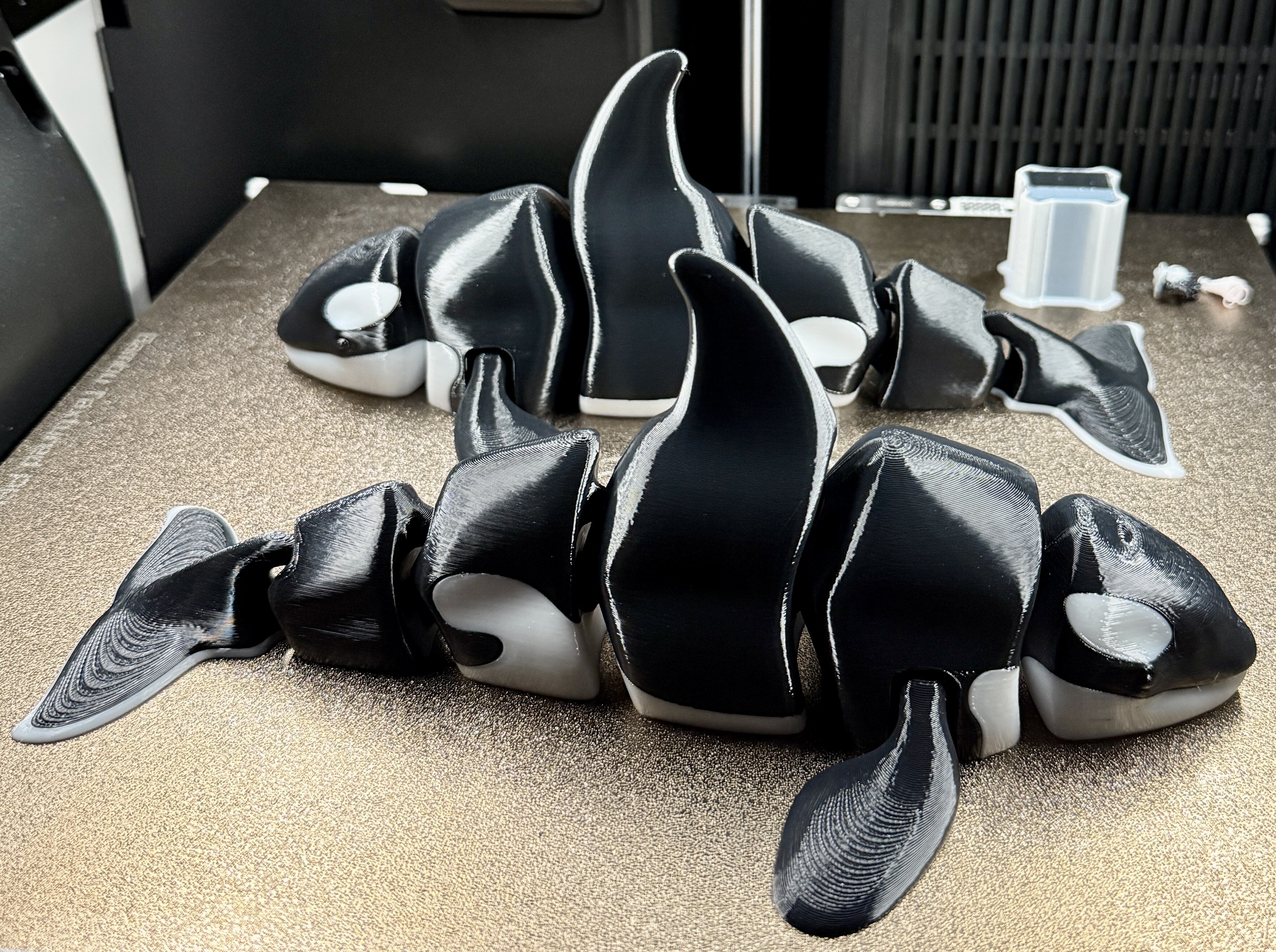
Got mine yesterday, so far, magnificent.
Other printers didnt have a vision encoder plate. They had e step calibrations. Same end result, but manually done by printing a cube and measuring x,y and z. Then inputting the offset. Also was free. This is what the xyz cubes are for. Maybe even better because you actually get to see the difference and dial it in perfect. Even for different filaments if you wanted.
Some of us asked why the previous bambu printers didnt have estep calibration, but Most users had no idea what we were talking about. “thats not needed anymore” or “thats a creality thing”, or “its as accurate as you can get” is what i heard at the time.
I do not fully agree with your statement.
You can tune your printer so the your calibration cube comes out fine, but that doesn’t necessarily mean that everything is correct. Flow calibration and other parameters influence the dimensions also.
Here an interesting video of Vector 3D digging into this topic.
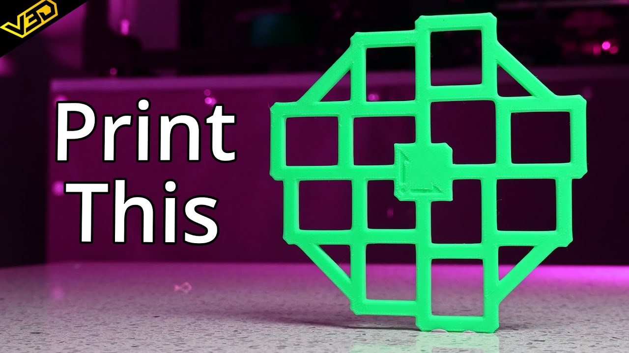
I was comparing it to the vision encoder plate that also doesnt account for those things.
The calilantern also adds skew. Otherwise its just a bunch of calibration cubes.
Does eStep compensate for non-linear effects? I’m pretty sure that the vision encoder plate either does, or at least could in theory if it doesn’t already. It seems better equipped to deal with the inevitable noise of an inevitably imperfect motion system that’s driven by belts. If nothing else, it’s giving me a higher confidence by measuring optically the nozzle position, which is what we all care about most, not an input to the motion system.
Maybe I’m under-rating eStep, but I don’t see how it could compete.
The end result is whats important. Estep calibration includes filament, so may give a better end result and can be done for different filaments. Covering things like shrinkage at the same time. The plate only calibrates motion. Still have to compensate for shrinkage afterwards. The plate may give a perfect motion system that still makes parts that arent the correct size. Now if the printer could print a cube and then measure that cube afterwards, and do its own shrinkage calibration, that would be awesome.
Say you want a perfect 20mmx20mmx20mm cube, esteps will get you there. With any filament you test. The plate may not. But the plate will probably make perfectly sized cf and gf parts because they barely shrink at all. extruder estep calibration is also nice.
Without a doubt, the vision plate will not do anything to compensate for shrinkage. That’s a separate, completely independent calibration to be done after the vision encoder plate calibration.
I realize you’re aware of this, but I added the emphasis for anyone else who may be reading, as even Aurora Tech Channel got confused by this.
At least in my head, it’s a lot cleaner to maintain the independence between the two calibrations. If one starts conflating the two, whether by eStep or some other method… it’s not clear to me how to think about that. It seems like you might get a messy average, but I don’t see how it can be as accurate, unless you’re limited to objects the size of your calibration object. So, to take it to an extreme, if you only wanted to print 20mm calibration cubes, one after another, all located in the the exact same spot (say the center of the build plate), for sure you could dial it in to do that very accurately. But if you then wanted to do a 150mm cube, potentially located in all different spots on the build plate, as an example, you lose that accuracy, whereas you wouldn’t with the the separate vision encoder plate accuracy and separate shrinkage compensation accuracy. Right? That’s where the rubber meets the road, so to speak, in terms of clarifying the distinction.
Am I wrong? If so, please someone do correct me. But that’s my operative assumption at this point.
That is correct in my opinion.
Here an example:
You compensate your calibration cube with E-steps so it is exactly 20mm.
But in reality your motion is 0.2mm too small, but that deviation is not measured because your flow is set too high.
When you would print something of 10x the size (200mm) your negative deviation would be approximately -2.0mm (10x 0.2mm) you would end up with a dimension of 198mm + 0.2mm over extrusion = 198.2mm.
This is a sample with over extrusion. Under extrusion would work the other way.
In my opinion you first need to calibrate motion system, and then your profile and shrinkage.
And even those two could influence each other.
To my opinion shrinkage should not be compensated in motion system but with scaling in slicer.
Otherwise you need different E-steps for different filaments. That can’t be the solution.
Very interesting video. Is it possible to apply this method on our Bambu Lab printer as well?
@Avarax I do not know if H2D allows for manual E-step and/or skew correction.
Mine is hopefully to arrive next week.
I love mine! Honestly! I’m enjoying PETG CF and ABS prints so far that are flawless for fdm. I actually printed some desiccant holders overnight with PETG CF, and when I pulled them off this morning, I honestly had to just sit and look at them for a minute. They looked that damn good!
Given, I increased my chamber and bed temp a little, but that’s all part of learning a printer, and it took me what, 5 minutes to change both profiles… And if it’s anything like both my P1S units, those settings will work for the vast majority of what I print. I first no problems venturing well into polycarbonateand nylons, as a learning step(I’ve done a few nylon prints on the P1S’s, but they were not up to how I like my final prints to look}.
But this machine… It’s something else! I think it has allot of settings that a beginner could stumble on tbh, but that’s any machine with the number of features of this one…
But I think it was a worthwhile investment for sure!
That brings up a good point. I believe the correct calibration sequence would be:
- Vision encoder plate calibration
- Flow rate calibration to eliminate (as much as possible) the over/under extrusion so it doesn’t interfere with the last step, which is:
- shrinkage compensation calibration.
Actually, to some degree, a good shrinkage compensation model will correct for over/under extrusion by using the two-pin measurement method (cf Clough42 for an explanation of that if unfamiliar with that approach for measuring center-to-center between two machinist pins), but, nonetheless, I still think it makes sense to reduce it as much as possible ahead of that if you’re ever going to do it at all. Here’s an example of such a shrinkage calibration model, one that I recommend:
You can even iterate using that model to get progressively more accurate shrinkage compensation plug numbers for your filament profile. I find that two iterations is generally enough, but I print a third as confirmation that I’ve reached the asymptote close enough.