Wondering how easy it is to add a .stl file that’s a logo, to a cup holder.
Ideally I’d like to have the cup recessed in a section and then be able to glue or click the logo into place.
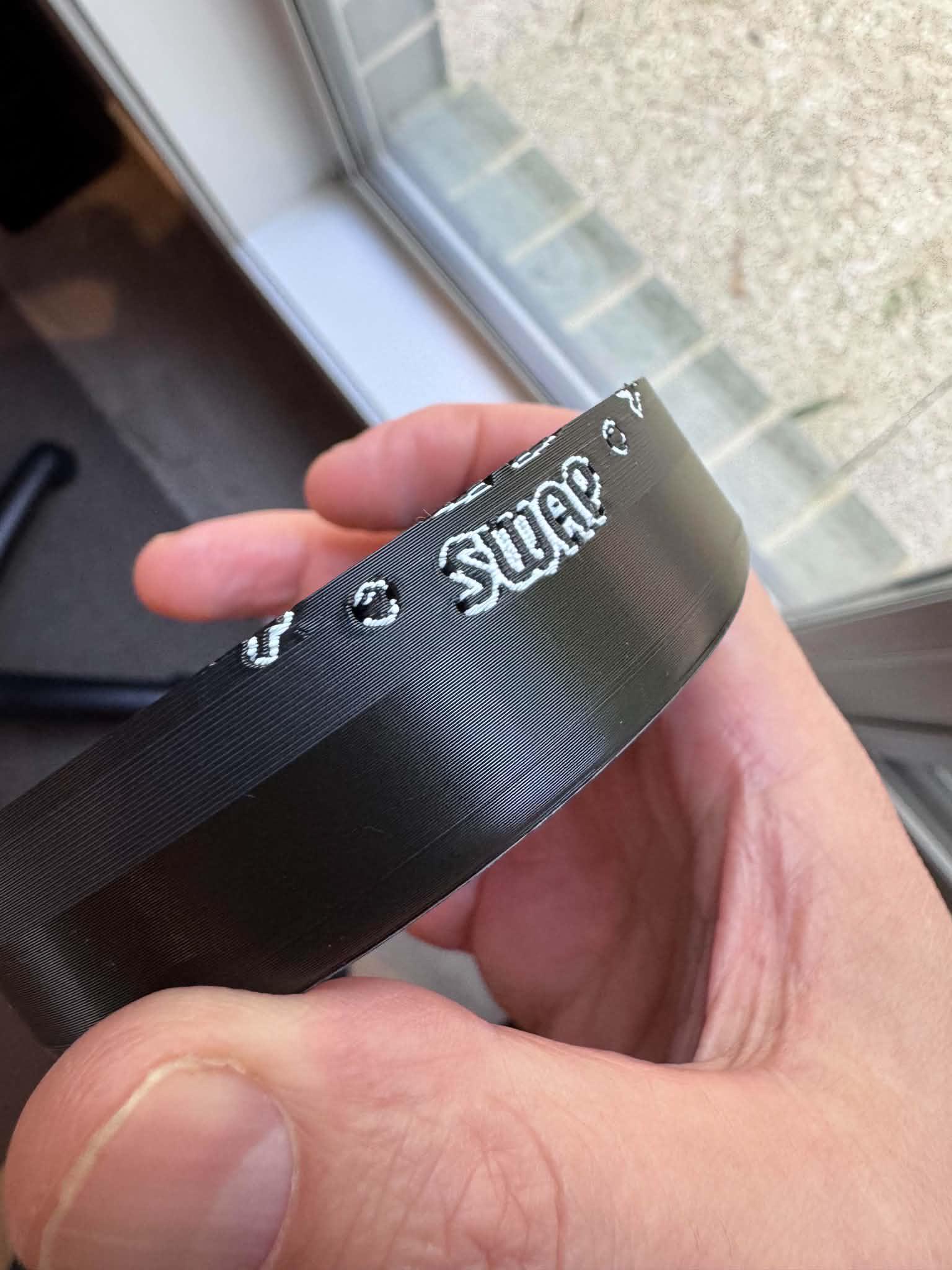
I’ve tried printing directly onto the cup but I get bleeding as shown below so looking for options.
Is any of this achievable in Bambu Slicer.
Using P2S with AMS2 Pro.
Just to be clear, I don’t want it too be one single print. I want the logo to be printed on a different plate and then have the ability to click it into place on the cup.
If there is an easier way or different idea happy to hear them.
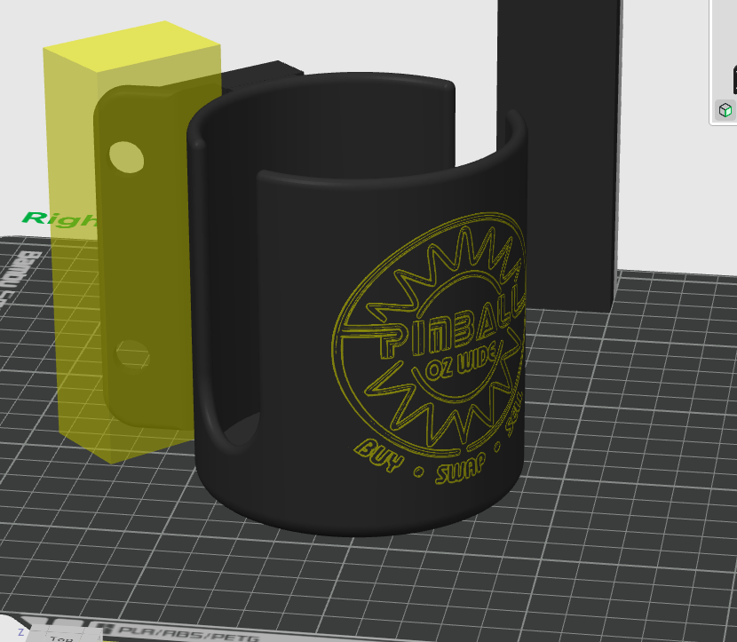
Last image is the cup with the logo as it stands
I wouldn’t do that in the slicer, no. Is may be possible but there are better modeling tools (pretty much any).
Assuming I don’t have the original model to start with (only a mesh or STEP), I’d probably create a cylinder matching the ID of the cup plus half the wall’s thickness, and a cube large enough to cover the logo vertically. Then do some boolean operations to get the logo area cut out as a separate curved piece of half the wall thickness, leaving a matching indent in the cup.
After that it becomes a question of tolerances… you may need to shrink or expand (scale) the logo piece a little so it fits into the recess to your satisfaction, both in terms of width/height and also thickness. Depending on filament, print settings, and so on. Will likely take some experimenting, especially since they’ll be printed in different orientations.
I’m not sure how thick those walls are, so maybe that’s not viable, or one of the parts needs to be thicker than the other.
For snap-in action I think it will need some kind of matching beveled edges or tabs/pins or similar… something to provide the snap.
I will add that I think one could still get a nice result just printing the logo on the side in the first place… with some tuning and slower speeds and perhaps finer lines or smaller nozzle. It’s definitely more challenging then top/bottom embedding, but can still look nice. One thing I found can help is to embed the text/logo at least one line width deep into the base object, keeping the edges painted with the same contrasting color(s). This gives it some more separation and still looks sharp. Raising the text/logo can work also, but that tends to wear off over time or just be annoying in the first place. And slow walls… and low accelerations, and a fractional Quality → Advanced → Smooth Coefficient.
Cheers,
-Max
Could you further give some feedback on what you said here -
“I will add that I think one could still get a nice result just printing the logo on the side in the first place… with some tuning and slower speeds and perhaps finer lines or smaller nozzle. It’s definitely more challenging then top/bottom embedding, but can still look nice. One thing I found can help is to embed the text/logo at least one line width deep into the base object, keeping the edges painted with the same contrasting color(s). This gives it some more separation and still looks sharp. Raising the text/logo can work also, but that tends to wear off over time or just be annoying in the first place. And slow walls… and low accelerations, and a fractional Quality → Advanced → Smooth Coefficient.”
My current settings are:
0.20 nozzle and my speeds have been reduced down by 50% basically across the board.
Can you explain the embedding bit, keeping it one line in depth…etc etc.
Do I presume when you say raising the logo/text you mean to have it print raised off the surface as opposed to flush with the object…how would I go about this as I only know how to do this from the TEXT drop down at the top.
Smooth Coefficient is currently set to 4?!? Do i lower this number based on the above?
Well, I don’t really know what you’re working with and wouldn’t want to send you on a goose chase, or whatever it is y’all chase down yonder. If you cold post your project file, that would be most helpful.
Small nozzle and slow speeds is a good start. What filaments are you working with?
How are you applying color? By painting, or is the whole logo part assigned a different filament directly (no painting)?
And how is the logo being wrapped around the cup? Was the outside radius already matched somehow?
In terms of embedding… by “one line width” I mean, for example if your outer line width is set to .24mm then embed the logo by at least that much.
As to how… again guessing on what you have, but I’d probably select both the cup and logo parts (positioned the way you have them in the 2nd screenshot) and perform a boolean cut, using the logo as the cutting tool and cup as the base object, and keeping the logo part (this could be done in Studio, boolean tool in top toolbar). What’s left should be a copy of the cup but with the logo cut out of the side, and the logo part. Then carefully move the logo part so it sinks into the cut in the cup by the desired embed depth. If the logo now sticks too far into the cup side (or perhaps through it), another boolean cut operation can be used to trim that off, flush in the back with the previously-created indent area.
Making it protrude out would be simpler, just moving the logo part out a bit from the cup side, no boolean ops needed.
Studio isn’t great for precise aliments, but if you orient the logo pointing exactly on X or Y axis, it should be pretty simple to align correctly (using digit entry in the move tool, not trying to drag things with mouse).
And yes, smooth coefficient to something like 0.5 and “Smooth speed discontinuity area” above it checked. This smooths out speed transitions, eg. between normal wall speed and overhangs/bridges (which you’ll have if logo is embedded or raised).
HTH,
-Max
I’m just mentioning this because you opened a very similar thread a week ago:
Let me put it this way: Even if you’re still avoiding it, my recommendation stands - you should at least give CAD a try, even if it’s just Tinkercad.
This applies to both your previous topic and this one: Bambu Studio is neither a modeling program nor a CAD program. It’s really only meant for slicing and making small adjustments that you may have overlooked.
Don’t be afraid of CAD - there are now plenty of easy-to-use programs out there that let you get started and bring your ideas to life. See also the old thread where you got tons of advice.
I’d second what the others are saying and especially in regards to a CAD or CAD-like software.
But from my perspective, trying to print graphics on the side of a cylinder while positioning the cylinder to optimize the printing of the cylinder body is not playing to the printers strengths.
Go to Printables.com or MakerWorld.com and do a model search on “Mug”, which I just did on Printables and you will notice a lack of mugs with printed graphics on the side. Should you find a model that fits the general idea of what you want to do, download it and see how the creator did it. You can then delete the file
As a practical matter, my observation is that what you want is more often relegated to a vinyl cutter like a Cricut type machine and/or a laser engraver. Lots of maker oriented machines types out there and they all have strengths and weaknesses
This youtube video demonstrates how to take an image file.
Convert it to SVG, import that into Fusion 360 (CAD) and then use it on a surface to extrude (or cut).
This will do both creation of an inlay object, and a cutout on your cup. You would need to add about 0.125mm of clearance between the two parts.
Before you do and try printing the whole thing.
Cut out the tricky parts and print SMALL sections of the model that you can test first.
This helps you to make progress faster and with less waste.
You could also try very small and simple things… Like make a thin walled, short, shot glass with a small logo on the side and try that to get it right. Then move to a bigger object.