I have ordered closed disc neodyme magnets and will try again, thanks for checking my working method, so it definately suggest the problrm is in my (possible deteriorated) inferior magnets, is there a way to inspect the magnet quality? In other words could it be the qase my magnets are coated ferrite ones?
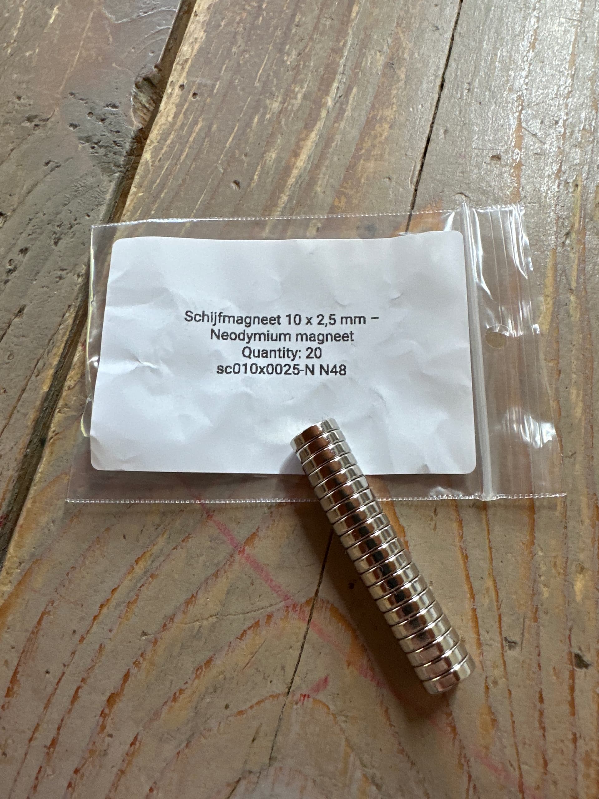
I am almost sure that those magnets will work better.
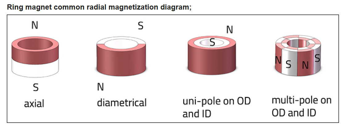
If your previous magnets were of type multi-pole (most right) then a slight rotation of the magnets might already cause issues.
Regarding the authenticity of the Neodymium magnets, I would simply trust that.
If you really don’t trust it. Remove the coating and make it wet. Ferrite doesn’t rust afaik and Neodymium does.
And what’s the result?
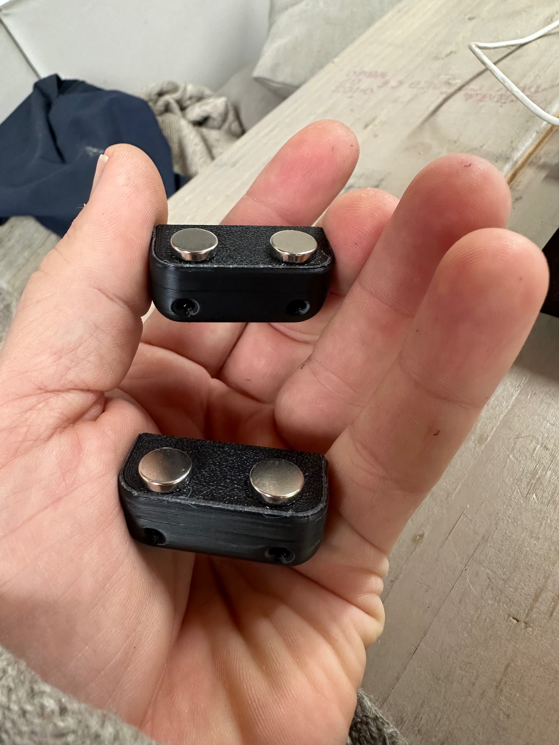
New neodyme closed disc magnets embedded problem solved! Thanks yall. I think I’ll make the pocket 10,15 to have a press install with less force to prevent bed movement layer distortion visibility.
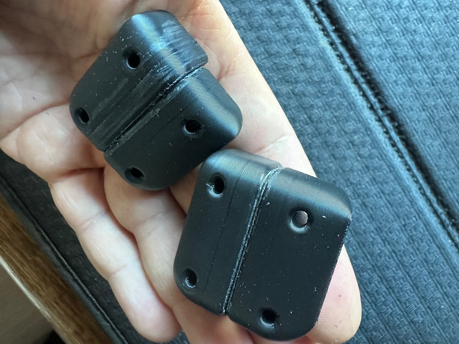
I think the open disc magnets weren’t neodyme or had something like multi vector polarity….
The reason I dont want to glue them is of course by owning a H2D I can! Using this embedded method also prevents loosening magnets or damage coating by slamming the door…
I can’t disagree with the “I can” statement, but making the pocket for the magnet slightly deeper and even make a tiny overhang at the top prevents them from touching each other.
You might want to read here for more ideas: Perfect Flush Magnet Fit - #7 by KYZ_Design
I just figured out the best pocket for a 10 x 2,5mm neodyme magnet is 10,15 x 2,8 mm. It is a snug press fit without the need for a lot of force and makes sure the magnets are resting 0.15 lower than the next layer height.
10,2 is to loose and results in a couple of spaghetti layers before the nozzle covers the mess
It’s even possible to fully embed magnets within a pocket so there’s a full layer of material covering them! Requires the part body to be split in two in CAD, then assembled together in the slicer.
You’re doing it in that photo. They stick together? Then they are working.
If you want to measure strength, oppose the poles on two and push them together. How hard they resist is an easy way to gauge strength.
Also, the easiest way to mark poles? With the magnets all stuck together like in the photo they are lined up N/S/N/S/N/S. You don’t know which end is N or S without using a known magnet as suggested earlier (and ignored), but you know the faces alternate. You can go right down that stack and mark all the faces pointing the same way with a dot. They will all be either the N or S pole. Then align in the model and pair marked with unmarked.
If you hadn’t been so set on an impossibility, and accepted the advice and information you asked for, you could have solved this much quicker.
And nice apology for saying we all had no idea what we were talking about and you’re welcome for the (nonexistent) thank you.
They said thank you.
An apology would still be nice though.
I didn’t. That was cold. The goal was just to show it wasn’t a big uniform field but instead made up of lots of small domains. And also to show that a build plate almost completely shields the print bed magnetic field from the print.
Currents in the heat bed are significant but they are AC. That’s really all you need to know for this problem to know it has nothing to do with the op’s issues (besides some magnet basics). AC magnetic fields demagnetize, not magnetize. Many may not be old enough but with old color tube TVs you had to occasionally degauss them to stop colors from misaligning. It was just a coil that plugged into the wall and produced an alternating magnetic field. Later TVs added coils to do that automatically. Same for tape erasers - alternating field.
If the heat bed was run off DC (it is not) then there might be some kind of magnetization possible but it would be in a uniform direction. OP was randomly inserting magnets and got it “wrong” every time. If the bed was DC and was strong enough to do what OP swore was happening, he would have probably gotten one to work just by dumb luck.
In theory it cannot unless your theory includes temperatures high enough to melt all the plastic in the build chamber and very strong magnetic fields focused on the magnets.
And inductive heaters use AC. Induction is an AC process. Inductive stoves and heaters use essentially a transformer to couple power into whatever is supposed to be heated. Transformers do not pass DC. They use AC and AC fields demagnetize. What would happen if there was an effect is magnets would gradually turn into little non-magnetic disks, rings, or whatever shape they are.
Inductive cooktops are a great example of an inductive heater. There’s a coil in the cooktop that creates a changing magnetic field above it that is captured by cookware. That changing field induces currents in the cookware that resistively heat. But it takes a changing field to induce those currents that heat. Or, move susceptible metal into a DC unchanging field and it will induce a current but only while the field strength is changing as you move the metal in and out of the field. Let it sit still and with a DC field, the induced current goes to 0.
This is how generators and alternators also work and why motion is involved. You create changing magnetic fields by moving coils or magnets relative to each other. But it’s always changing that induces currents and those kinds of fields demagnetize.
With a caveat. The full layer separates the magnets by the layer thicknesses involved. Magnetic attraction falls off by the cube of the distance between the magnets.
Not allowing the magnet faces to tough each other drastically reduces the attraction but whether that matters or not depends on the application.
thanks MZip. does not apply to OP (wrong printer). Only applies to magnetic fields.
I have not looked into inductive heaters. I expected the H2C to use AC voltage. The average magnetic field is zero. The only relevance the heat produced. Making it more susceptible to a sustained field. I expect the inductive heater would heat the inserted magnet. But only while heating over the magnet.
My original post was implying DC induction. Not with the average field of 0. Another thing to look into in my free time.
I’m not sure I follow but DC fields take some kind of motion to create current in something. Somehow you need a field changing with time. If everything is static there’s no current generated. Inductive heaters and such all have to be AC to work and with AC the average field is generally 0. 
Occahm’s Rasor - what is more likely:
- Human error (you didn’t place them in the right way, on accident)
- The magnets in H2 hotends (especially H2C induction coil magnets), under the right conditions caused the polarity of your inserted magnets to flip.
- Hardened Steel nozzels moving over the magnests, physically flipped them over.
- You are pulling an early April Fools joke on everyone.
I have the same magnetic sheet someone else posted a picture of.
If you’re going to do things with magnets, you need one. They’re cheap.
https://www.amazon.com/dp/B0952FJWNZ?th=1
In other words could it be the qase my magnets are coated ferrite ones?
Probably not. This is almost certainly because you assumed you had a simple North / South pole arrangement along the axis of your ring magnets, but they are actually something else.
Just like you assumed the “magnets” in the build plate are a simple orientation like having North facing up, and filling the printer with magenetic field. Which they do not. Like someone showed by holding that film up to the build plate, the build plate “magnets” are actually a plate of material with alternating lines of north and south poles. This is done because when you put the build plate on top the build plate ends up pulling 99% of those little fields into itself, creating a strong and even attraction over the whole surface rather than a few strong spots and nothing in between.
With the film you can also use the film to see for yourself that the kind of electric currents in a heating element barely register compared to either the build plate or even tiny neodymium magnets.
Using it on different things you’ll quickly find that most magnets are not made how you think they are. Probably including those ring magnets, which I suspect you “flipped” during installation by inadvertently rotating them in their sockets.
I think what you are saying is inductive HEATers need AC to generate heat. It is the change in field direction that generates the heat. DC creates a magnetic field, just fine. I am guessing the specific frequency to generate heat depends on the material. Sometimes the heat is the goal, sometimes it is undesirable. We are off on a tangent to the OP.
Why is this still a thing?
In an inductive heater, AC is used to generate a changing magnetic field. That field then couples the object being heated (which has to be ferrous, have the ability to be attracted to a magnet) where it induces “eddy currents” in that material, tiny little domains of electrical current generated by the changing field that then heat the material up. The only thing frequency does is control how fast the inductor heats things up. Higher frequency = faster heating but concentrated near the surface, lower frequency = slower heating that reaches deeper in to the object being heated. Frequency controls something called “skin depth”, how far the eddy currents penetrate in to the metal. It’s more about how the metal is going to be heated up (speed, depth) than the material itself. Like if the objective is to get the metal as hot as possible as quickly as possible, vs. heating to temper a region in the metal.
The heaters in our printers are not inductive (except for the H2C’s nozzle swapper). They’re simple resistive heaters that would work the same with AC or DC current.