External studs print about 0.20 mm undersized across PLA, PETG, ABS and PC
Evidence package: four figures, the exact model, native sliced project and actual G-code are included. Dimensional annotations distinguish independently measured coordinates from Bambu’s own UI labels.
Summary
I am investigating repeatable undersizing of small external studs printed with a 0.2 and .4 mm nozzle (this report includes evidence from the .2mm nozzle). Every stud on the tested boards measures undersized, and I have observed the same approximately 0.20 mm shortfall with PLA, PETG, ABS and PC. The attached new 5.00 mm reproduction model retains a 5.000 mm mesh diameter. Its actual Bambu G-code indicates an approximately 5 mm extrusion envelope, not a 4.8 mm target. Please investigate where the size difference is introduced; the current evidence does not isolate firmware, extrusion, motion or calibration as the cause.
Physical observations
These are my caliper measurements and fit observations from previous prints, not measurements inferred from a slicer preview.
| Previous nominal stud diameter | Measured printed diameter | Result |
|---|---|---|
| 5.10 mm | 4.90 mm | Too tight with actual LEGO pieces |
| 4.80 mm | 4.60 mm | Too loose; no useful clutch |
| 5.05 mm, small underside holes (R36) | 4.80 mm | Excellent clutch with actual LEGO pieces |
I measured every stud on the 4.80 mm test plate and reported the same undersizing across the other tested board. I also measured official LEGO studs at approximately 4.80 mm. The first two comparisons each differ by 0.20 mm; the later 5.05-to-4.80 result differs by 0.25 mm. These observations are preserved as reported rather than forced into one exact correction factor.
I have observed the approximately 0.20 mm issue across PLA, PETG, ABS and PC. A controlled per-material table with raw readings, exact profiles and printer logs was not recorded for this report. This cross-material consistency makes material shrinkage alone a less convincing explanation, but does not establish a particular cause.
The attached R38 5.00 mm coupon has been modeled and sliced but has not yet been physically measured. It is a diagnostic reproduction file, not a claim that a new 5.00 mm print already measured 4.80 mm.
Reproduction environment and settings
| Item | Verified value in the attached reproduction |
|---|---|
| Slicer | Bambu Studio 02.08.04.57 Beta, native Windows CLI and desktop Preview |
| Saved printer profile | Bambu Lab H2C 0.2 nozzle |
| Nozzle / layer height | 0.20 mm / 0.10 mm |
| Normal / outside line width | 0.22 mm configured; selected emitted width 0.21999 mm |
| Filament profile | Black PLA Tough+; saved filament diameter 1.75 mm |
| Filament / print flow ratio | 0.98 / 1.00 |
| Infill / ironing | 100% / OFF |
| Auxiliary cooling | 30%; model commands S0 and S76 |
| XY contour / hole compensation | 0 / 0 mm |
| Auto circle contour-hole compensation | OFF |
| Wall generator / slice resolution | Arachne / 0.012 mm |
| Precise outer wall | OFF |
| Firmware and printer-side calibration | Not captured; no claim that these match saved settings |
Geometry: one 6 x 6 stud coupon, 48 x 48 mm functional footprint plus an identifying tab; 1.00 mm base, 1.80 mm stud height, 2.80 mm total height, 8.00 mm pitch. Each small centered underside blind hole is 2.60 mm diameter x 1.70 mm deep, leaving a 1.10 mm closed cap. There are no lower-clutch tube structures. This file is black only. The native slice completed without warnings.
Four-image evidence
1. Saved STL geometry
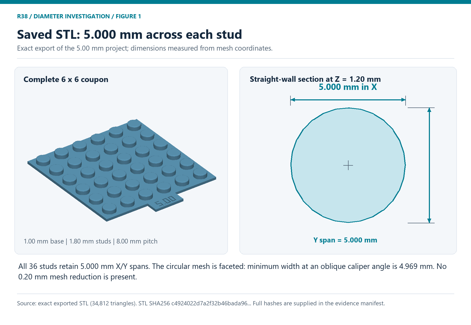
The STL is exported from the actual saved 3MF mesh and checked by re-reading its coordinates. All 36 straight-wall sections measure 5.000 mm in X and Y. The retained circular mesh is faceted: its minimum oblique caliper width is 4.96856 mm. This small mesh approximation is documented and is not a 0.20 mm reduction.
2. Native Bambu preview and re-exported mesh
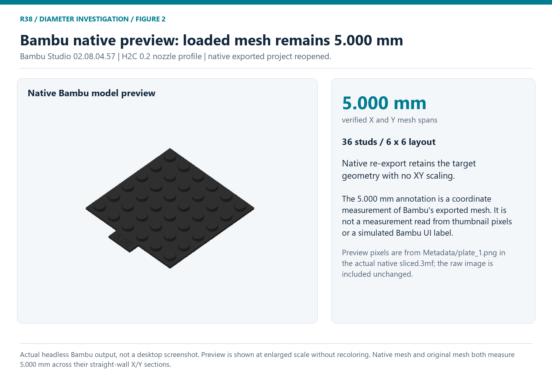
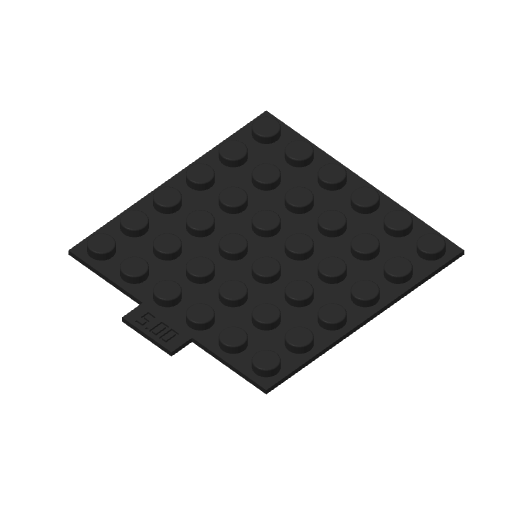
The preview comes directly from Metadata/plate_1.png in Bambu’s actual exported sliced.3mf; the raw native PNG is also attached. Reopening that native project confirms 5.000 mm X/Y straight-wall spans for all 36 studs. The dimensional caption is an independent coordinate measurement, not a Bambu measurement-tool readout or a measurement from thumbnail pixels. This is native headless output, not a desktop screenshot.
3. Actual sliced extrusion paths
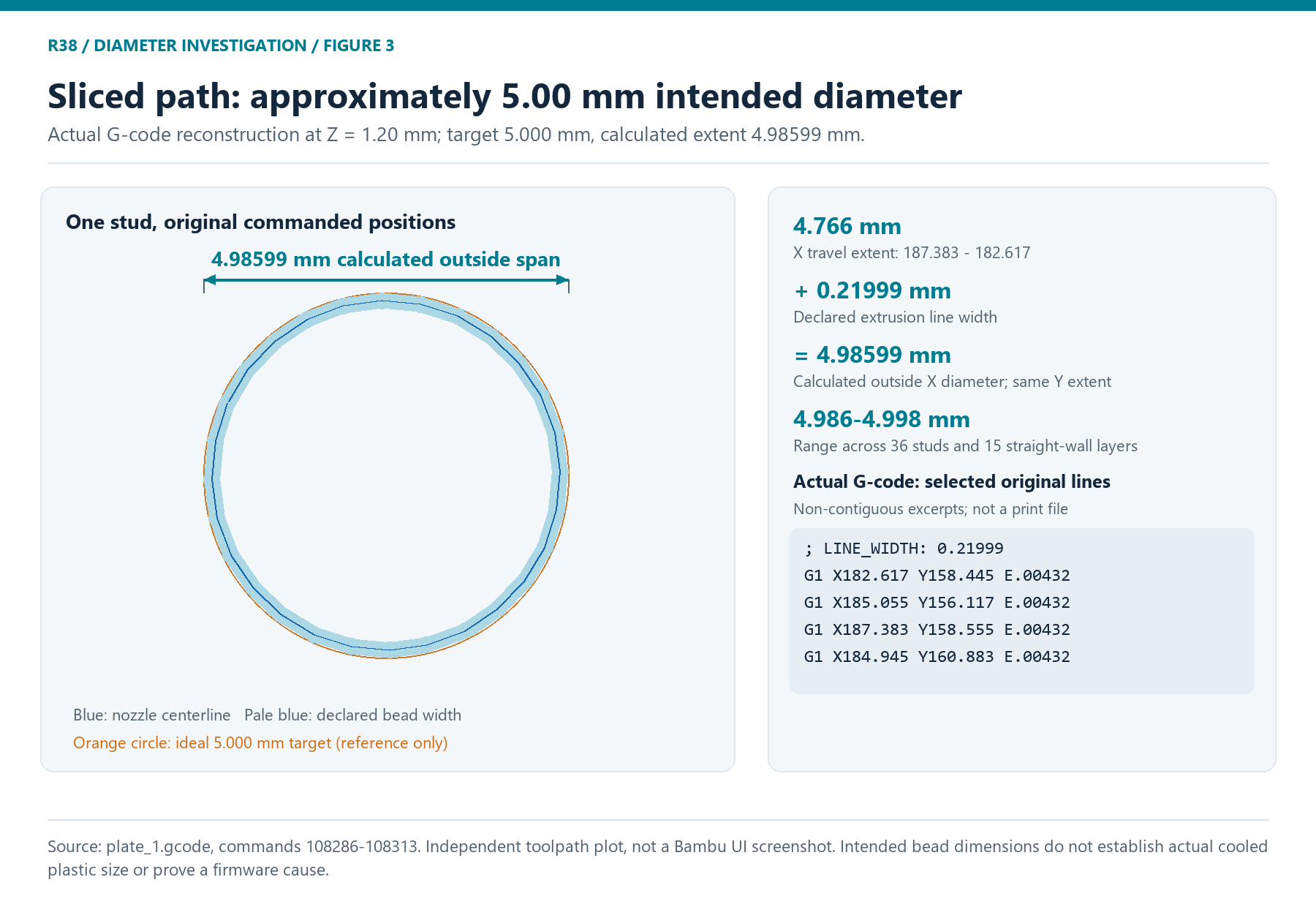
This is an independent rendering of the actual G-code, not a simulated Bambu UI screenshot. All 36 studs x 15 straight-wall layers = 540 contours were checked. X/Y nozzle-centerline extents plus the declared bead width give 4.98599-4.99799 mm, approximately the 5.00 mm target. The bead width must be included: the nozzle centerline alone is intentionally inside the outside surface. The rounded crown is not used for the straight-wall measurement.
4. Native Bambu post-slice toolpath Preview

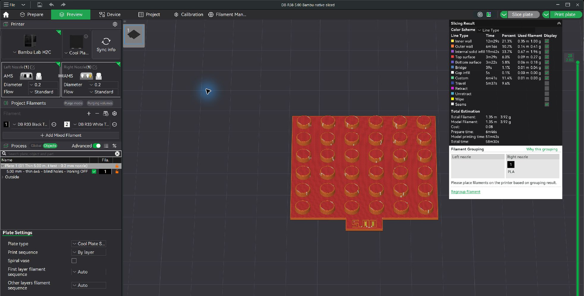
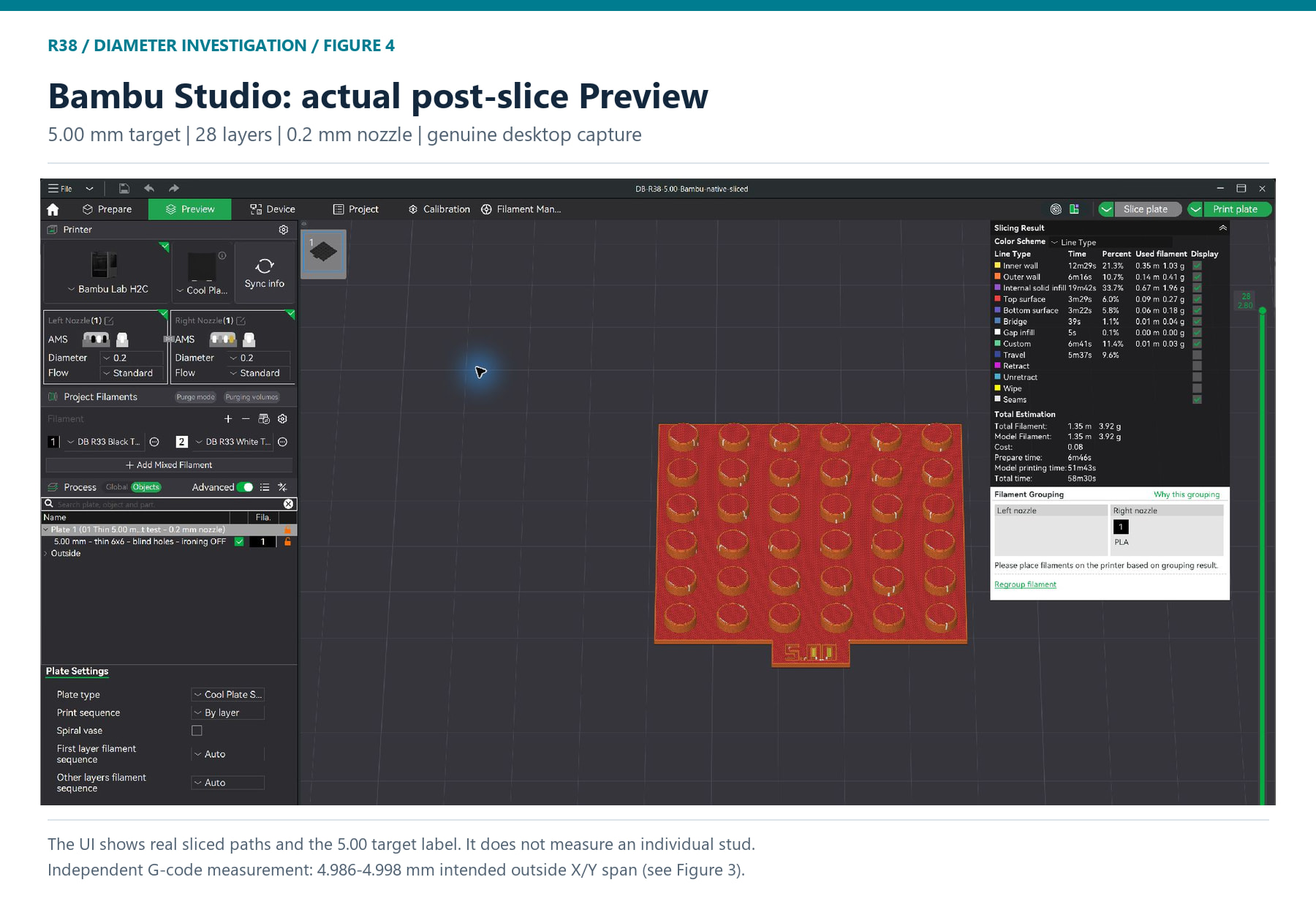
This is a genuine desktop capture of Bambu Studio’s Preview tab, showing Line Type colors and all 28 layers through Z2.80 mm. The native summary shows 58m30s / 3.92g. The previously saved sliced project was opened directly; no new slice or printer command was sent for this screenshot. Its 5.00 object name and engraved label identify the nominal design. Bambu’s Preview does not display a native individual-stud diameter measurement here; the separately verified mesh is 5.000 mm and its calculated G-code envelope is 4.986-4.998 mm. The caption does not pretend those measurements are a Bambu UI readout. The image is cropped only below the relevant application content to exclude an unrelated desktop notification; the unannotated application crop is included.
Actual G-code excerpt
Source: DB-R38-5.00-Bambu-actual.gcode, original command lines 108286-108313, at Z = 1.20 mm. The selected stud is centered at X185, Y158.5. The position before this excerpt is X182.829, Y159.484. M83 (relative extrusion) is active from original line 1131.
The active feature comment was at original line 108283; the active line-width comment was at line 108248. They are gathered above the unchanged consecutive command lines below for clarity. This excerpt is not a standalone print file.
; FEATURE: Outer wall
; LINE_WIDTH: 0.21999
G1 X182.664 Y158.977 E.00432
G1 X182.617 Y158.445 E.00432
G1 X182.689 Y157.916 E.00432
G1 X182.877 Y157.417 E.00432
G1 X183.171 Y156.971 E.00432
G1 X183.557 Y156.603 E.00432
G1 X184.016 Y156.329 E.00432
G1 X184.523 Y156.164 E.00432
G1 X185.055 Y156.117 E.00432
G1 X185.555 Y156.19 E.00409
G1 X186.088 Y156.38 E.00458
G1 X186.529 Y156.671 E.00427
G1 X186.897 Y157.057 E.00432
G1 X187.171 Y157.516 E.00432
G1 X187.336 Y158.023 E.00432
G1 X187.383 Y158.555 E.00432
G1 X187.311 Y159.084 E.00432
G1 X187.123 Y159.583 E.00432
G1 X186.829 Y160.029 E.00432
G1 X186.443 Y160.397 E.00432
G1 X185.984 Y160.671 E.00432
G1 X185.477 Y160.836 E.00432
G1 X184.945 Y160.883 E.00432
G1 X184.416 Y160.811 E.00432
G1 X183.917 Y160.623 E.00432
G1 X183.471 Y160.329 E.00432
G1 X183.103 Y159.943 E.00432
G1 X182.844 Y159.51 E.00408
For this loop:
X nozzle-centerline span = 187.383 - 182.617 = 4.766 mm
Declared line width                          = 0.21999 mm
Intended outside X span                     = 4.98599 mm

Y nozzle-centerline span = 160.883 - 156.117 = 4.766 mm
Intended outside Y span                     = 4.98599 mm
The E values were also analyzed, not just X/Y positions. Summed commanded filament volume divided by the nominal non-bridge path volume is 0.980423, consistent with the saved 0.98 filament flow ratio to command rounding. This is a volume factor, not a 2% XY scale. The calculation uses the installed-version Bambu non-bridge extrusion-area formula: area = height * (width - height * (1 - pi/4)). An extrusion-width comment expresses intended deposition; it does not prove the cooled plastic attains that width.
Expected versus actual
- Expected: the physical straight side of an approximately 5 mm external stud should be close to its commanded/model size within the printer’s applicable dimensional tolerance. An unexplained, repeatable approximately 0.20 mm reduction materially changes the fit.
- Observed on previous prints: 5.10 mm became 4.90 mm and 4.80 mm became 4.60 mm across the tested boards; a later 5.05 mm cavity coupon measured 4.80 mm and fit well.
- Verified in the new reproduction: a 5.000 mm mesh persists through native Bambu re-export, and the emitted X/Y paths plus declared extrusion width remain about 4.986-4.998 mm. The artifact does not contain a 4.80 mm straight-wall target.
- Not established: this does not prove that firmware misreads G-code, nor rule out extrusion calibration, flow behavior, motion calibration, pressure dynamics, actual nozzle condition, measurement effects or material behavior. The physical cause remains unresolved.
Reproduction and requested investigation
- Open
DB-R38-6x6-Thin-5.00-0.2mm.3mfas a project in Bambu Studio using the saved H2C 0.2 nozzle profile. Preserve its dimensions and settings. - Confirm the 5.000 mm straight-wall mesh spans. The supplied STL provides the same mesh without printer settings; use the 3MF for reproducing the supplied settings.
- Slice and compare the result with the attached actual native G-code. The supplied file was generated by version 02.08.04.57 and completed without warnings.
- For a hardware reproduction, use the correct machine/material profile, record the actual firmware, calibration and any overrides, then measure the cooled straight stud sides in both X and Y. No print was started as part of this software inspection.
- Please check whether any hidden contour offset, slicer path handling, firmware motion behavior, or extrusion/calibration effect could produce a similar absolute undersize across PLA, PETG and PC. Please advise what diagnostic logs or controlled print would distinguish those possibilities.
The attached new reproduction is PLA-profiled. PETG and PC observations refer to prior prints; this package does not pretend that one PLA profile documents all three materials.
Attachments and integrity
- This report as Markdown and PDF.
- The four full-resolution numbered PNGs above, raw native model previews and the unannotated desktop Preview crop.
- The original 5.00 mm project, exact exported STL, Bambu native sliced project, full unchanged G-code and exact excerpt.
- Machine-readable geometry, native-slice, toolpath and X/Y/E checks, with source hashes and a package manifest.
5.00 mm project SHA256:
c12a2d2b63923853344501939ee8f2f212db85dad3fcf4c244d75f8bb038b2b0

Actual native G-code SHA256:
8c2ef6e2c08dfb99764f8651c85cd11fc47ee6e5ccb11ef42d78145eb3721771
The accompanying 5.025 mm R38 test is separate from this bug reproduction. Both targets remain distinguishable after slicing: all 1,080 paired X/Y comparisons are larger for 5.025 mm, with a median difference of 0.026 mm. This verifies representable paths, not a guaranteed 0.025 mm physical printing accuracy.
DB-R38-6x6-Thin-5.00-0.2mm.3mf (349.2 KB)
DB-R38-5.00-Bambu-native-sliced.3mf (1.5 MB)

 &
&