I assume the main printer part detaches and the laser replaces it.
Look at the front of the toolhead. looks like a mount. Something slides down onto it
1 Like
The possible technical implementation of the extruder is really quite interesting.
To me, it looks like there is a centrally driven large drive gear, with the corresponding gears for each extruder (left and right) positioned on the outside. Both levers appear to be mounted at the bottom. At the top, where the small gear is located, there could be something like a cam mechanism integrated.
This would result in two operating modes:
- When switching from the left to the right extruder, the cam is in a neutral position, and both levers are pushed against the central drive gear by the spring in the middle.
- If the drive gear now rotates clockwise, the filament on the left side is retracted while the right side is engaged and pushed forward.
- Once the filament on the left is sufficiently retracted, the cam rotates toward the extruder that should be disengaged (in this case, the left extruder). This causes the left extruder to lose contact with the central gear, stopping further retraction.
This is just an assumption based on the images, but it would really be a very compact solution, and I find the possible implementation extremely interesting.

Wow, the extruder is extremely complex. It is quite a genius system. No wonder it took so long to design. It does bring up questions of reliability factors. This system reminds me of the A1 toolhead with the buckle in nozzle, the part cooling fan placement and design. Even the silicone sock is the same.
H2D Toolhead Nozzle Closeup:

A1 Toolhead:

What’s the problem with them?
@hpinvent So, it does have a built-in motor in the printhead for swiching between the nozzles? That would be faster than the I-Fast approach, which has to slam the printhead into the side of the enclosure (similar to how the X1C cuts filament) to toggle between the hotends/nozzles.
Since theres a few of the same topic now, ill post this here.
To add to my post below. You can see the tiny linear rails that the nozzles ride on
Where do you see the worm drive ?
I see a motor in the top left corner which seems to have a planetary gear setup in integrated. The metal gear at the motor’s output transfers motion to the small black gear located in the upper central position of the carriage.
I think what can be interpreted as a worm drive is actually a spring.
Because with a worm gear, movement could only be transferred in one direction, from right to left.
A cam at the top could, depending on its position and shape, allow both extruders to engage simultaneously, as I described earlier, or engage only one of the two extruders at a time.
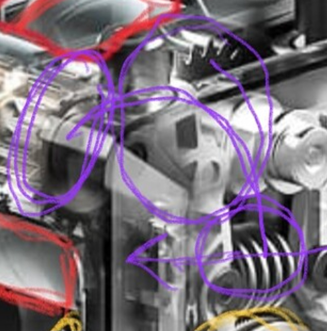
I circled them in purple. The worm gear would be the one mounted between the 2 arms.
Probably not technically a worm drive. But basically the same thing only instead of a spiral screw, it would just be straight teeth on the straight gear.
This type of gear has high holding torque all by itself. Like in a rock crawler that can also go in reverse

Or its just a spring and the center straight cut gear behind it does something else
1 Like
That is right if the worm gear is the driven gear, but if I understand your drawing correctly it would be the receiving gear
My idea was that by rotating the yellow cam (which is connected to the black gear in the top center), you could control the engagement of the extruder.
let’s assume that the middle component is a spring and not a worm gear. in that case, both levers would always be pulled inward, keeping both extruders engaged with the large central extruder gear.
- if the cam is rotated to the right (as shown in the image), the right lever is pushed outward, disengaging the right extruder (you can maybe slightly also see the roller at the lever where the cam is pusing against to reduce wear).
- if the cam is rotated downward, both extruders remain engaged, and filament would be pushed on the left side while being retracted on the right (assuming the large extruder gear in the center is rotating counterclockwise).
this could allow for an extremely fast filament swap, making tool changes nearly instantaneous.
for a nozzle switch based on the image shown below, you would only need to quickly rotate the cam downward and change the rotation direction of the central extruder gear.
this way, the left extruder would retract while the right extruder simultaneously feeds filament. once the filament on the left side has been sufficiently retracted, the cam would simply rotate to the left, disengaging the left lever from the central extruder wheel.
with the solution you described, this wouldn’t be possible, as both linked levers could only be shifted together from left to right. that would mean the two arms couldn’t be controlled independently. ![]()

1 Like
Nice,Bambu Lab CEO was quite clear about the upcoming model.
Youre probably right. Kinda lol. Not saying youre wrong. Just having fun with the puzzle. So now, to me, it does look like the lower thing is a spring. A spring can push and pull though. I dong think the extruder is responsible for extracting the previous used filament side. I think it just releases and the ams pulls back. Or it retracts before disengaging. But cant do both at the same time.(insert new filament and retract old.)
These 2 gears, along with the geared micro servo probably do the rocking.
Good eye

Either way, I think I see 17 precision cut gears$$$ and weight
1 Like
It looks as though it may have some way of capping off the nozzle that’s not currently engaged, in order to avoid oozing while keeping the hotend at temperature. Similar, at least notionally, to how the anker prototype printhead worked (well, 2 out of 6 worked).

so no time is lost reheating or nozzle wiping.
1 Like
Yeah I thought the same ![]()
if you look closely, you might notice what appears to be an arm extending into the middle of the carriage (shown in green).
it is attached to the top side of the ooze shield, ensuring that the shield always hangs downward. the purple objects look like they could be magnets, which might serve to fix the position and apply tension to the front part, pressing it against the nozzle opening.
the question now is how a switch to the right side would work.
this is where the idea of the green support arm and the pivot-mounted ooze shield comes in. if the arm is simply rotated counterclockwise to the right, it could snap into place on the right side, possibly with the help of the magnets on the right carriage side, positioning itself correctly to cover the right nozzle.
all just speculation, but so far, i haven’t found a better explanation.

1 Like
The ooze capping seems like a big deal. Anker tried it but folded before they could bring a full product to market. Any other vendor done it?
1 Like
The Prusa XL is the big one and some custom 3d printers have this too.
2 Likes
The idex ratrigs have the same sort of setup as the xl. silicone parking spot at each end of the x axis. also has some silicone ridges, so as it pulls away, it gets a little wipe

2 Likes
I’d be very keen to see the above mentioned printers race one another. By that I mean: for equal print quality, compare total print times. Kinda similar to what Aurora Tech channel tries to do.
1 Like
Prusa xl would win on quality but the ratrig would win on speed. especially on dual material prints. The ratrig swaps heads at 600mm/s. One tool shoots over to the parking spot at the same time as the other toolhead moving into print position. literally 1 second tool swaps. with no prime tower. Plus 4 xy motors that are fast af ldo motors.
The xl has heavy tool heads(partially due to the giant extruder gear set) so cant accelerate fast without massive smoothing for input shaper being needed. Heavy head and gantry is very bad. Its why its so amazing when a 350mm printer or bigger makes fast good prints. like the k2 with its closed loop steppers. The xl is just a money saver that prints really well. The time savings really shows up by adding more colors. Turtle n hare situation. Even 2 or 3 colors on a smaller part, will beat a bambu at a much lower print speed. The larger that part(lower color change to print time), it starts to sway back in the other direction. keep adding colors and the time savings gets comically good. If they can run the mmu3 to one of the heads and make a laser module… But probably not. Doable but Im not sure even the mmu3 has been done yet
2 Likes
I don’t think it matters which is drive and which is driven, for two reasons:
-
Holding torque applies when there is no drive torque being applied
-
The reason worm drives can’t be back-driven is that the the friction torque resisting motion is proportional to the backdrive torque (more torque pushes the teeth against each other harder), and the shallow tooth angle results in it always being higher than the torque trying to backdrive it.
1 Like