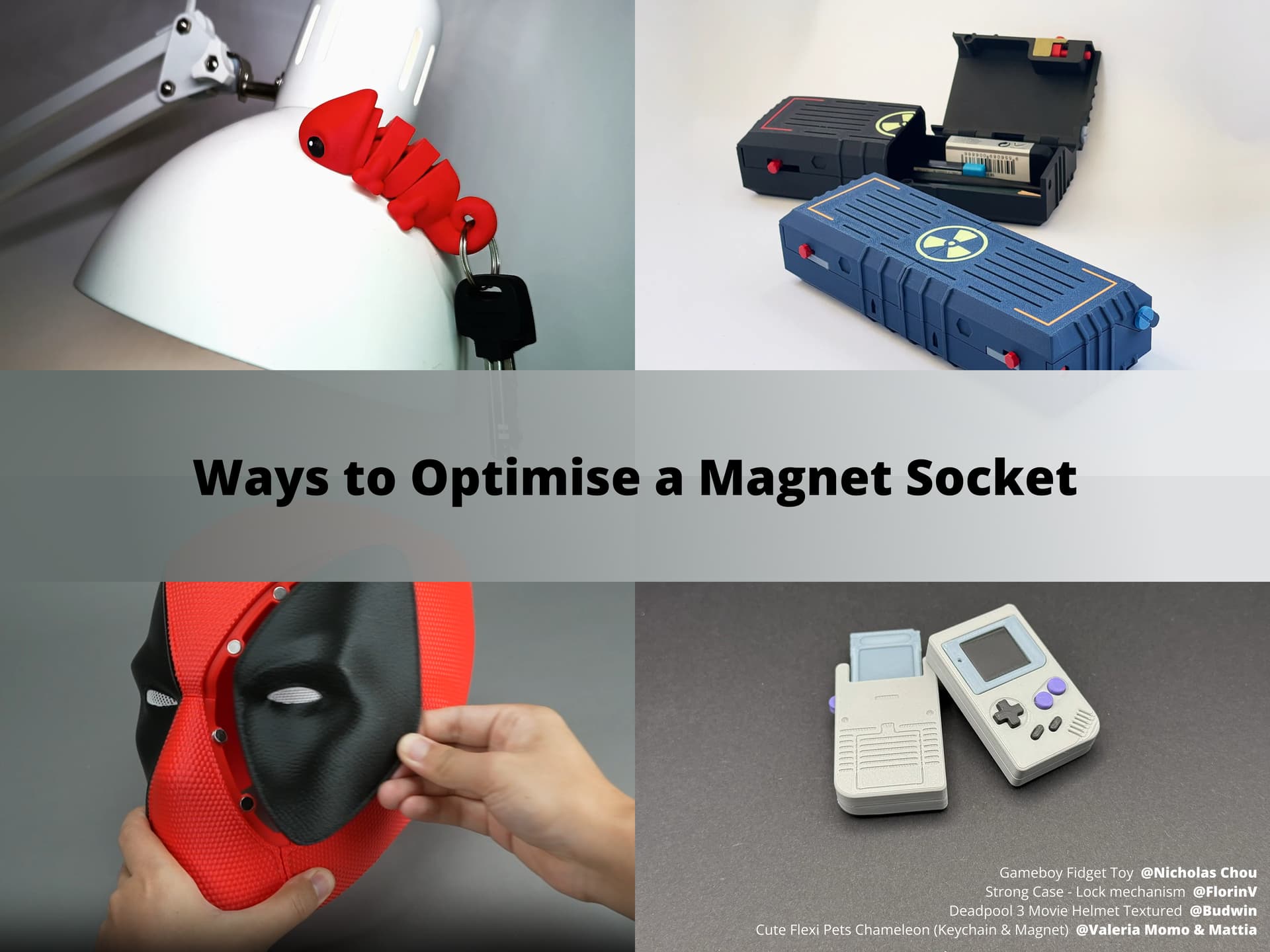
Have you ever used round magnets and circular magnet sockets in your 3D prints? This practice seems simple. But you might still encounter some difficulties during installation. Why do we experience these issues?
One of the reasons is that magnets vary in size. Additionally, minor design deviations and the printer’s accuracy limits affect how well the magnet fits the socket.
Besides the factors mentioned above, material shrinkage during printing also affects the print results. You may have noticed that the material shrinks during printing. It causes the magnet socket to become smaller and makes it hard to insert the magnet. It is often assumed that this problem can be fixed by considering material shrinkage in the design. However, merely testing and compensating for material shrinkage during design cannot fundamentally solve the issues. This is because variations in printers, materials, and environmental conditions can affect material shrinkage and final dimensions. To solve this problem, we need to begin with structural design and make it better at handling changes in size. This ensures smooth assembly.
Therefore, next, let us go through three practical structural design techniques to improve installation efficiency.
- Add a relief feature
- Design a blind pouch
- Schedule a pause and embed magnets
Add a relief feature
If the magnet socket is small in depth and diameter, we suggest adding relief features to its wall. Especially when the socket is placed on structures like ears or posts. Relief features are easy to design and require minor modifications to the model. They cut into the wall, providing space for deformation. It also helps reduce the effects of material shrinkage and thus improves adaptability. Additionally, the relief feature provides a path and space for excess glue when gluing the magnet. It helps prevent glue from spilling. You can see the installation effect of the magnet socket with the relief features in the image below.
For detailed information on the design size of the relief feature, please see the guide below. We suggest making the magnet socket’s diameter a bit larger than the magnet itself.
- Magnet socket diameter = Magnet diameter + 0.2 mm
- Magnet socket depth = Magnet thickness
- Width of the relief feature: 0.4 mm - 0.8 mm
- Length of the relief feature: 3 to 5 times the relief feature width
- Relief feature depth = Magnet socket depth
Important Notes
To enhance magnet stability, we recommend using a strong glue that sticks well to both metals and plastics. Avoid using glue designed only for plastic, as it may cause the magnet to come loose.
When using glue, please note:
- Handle with care to avoid contact with eyes and skin, especially when using runny glue.
- Use an appropriate portion to avoid overflowing.
- Choose thick super glue (CA glue) to avoid overflowing or splashing.

Design a blind pouch
The blind pouch design is a clever and efficient method to secure magnets. The blind pouch features a cavity with a thin cover, which firmly locks the magnet in place.
Joseph Willis also introduced the blind pouch design in his video. Check out the video 'Top 5 Ways to Add Magnets to Your 3D Prints! '. The image below shows a cross-section of the blind pouch and the positioning of the magnet inside it.
The blind pouch design offers the following benefits that make it ideal for installing magnets in 3D prints.
- You can insert magnets from the side or back of the model. It simplifies the assembly process.
- The cavity can be slightly larger than the magnet. This helps to avoid installation difficulties caused by tight fits.
- A thin top layer (approximately 0.4 mm) secures the magnet. This helps to enhance the stability.
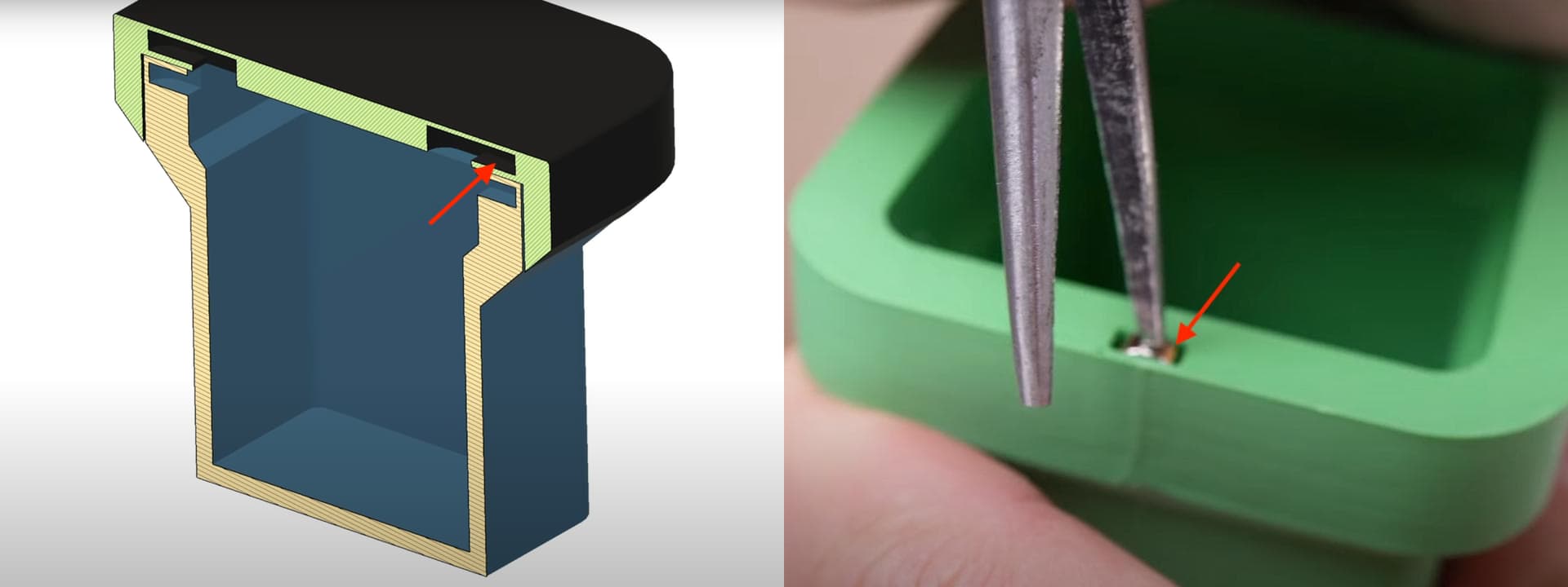
To make the most of the blind pouch design, we need to consider its features and the situations where it works best. Now, let’s take a look at two common blind pouch designs: putting the magnet in from the side of the model and putting the magnet in from the back of the model. This may assist you in selecting an option that meets your design requirements.
- Putting the magnet in from the side is suitable for edge positioning. It helps to keep the front and back surfaces clean and tidy.
- Putting the magnet in from the back is better suited for flat surfaces. It aids in maintaining a neat and clean side.
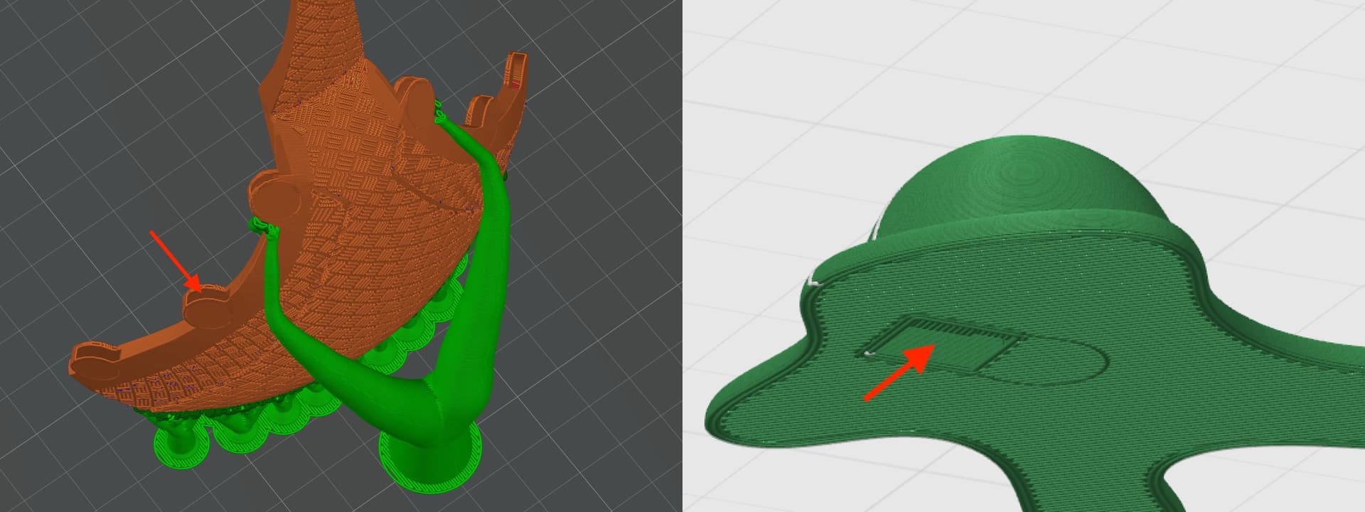
Having learnt about the benefits of the blind pouch and its common designs, let’s now focus on sizing the magnet socket.
To make it easier to understand, we have split the blind pouch from the main model to help you quickly identify the specific structure and location when reviewing the sizing recommendations. Please see the image and recommended dimensions below to ensure accurate construction.
- Contact surface
- Keep a top contact surface 0.4 mm in thickness
- Central cavity
- Cavity diameter = Magnet diameter + 0.4 mm
- Cavity height = Magnet thickness + 0.2 mm
- Tunnel
- Minimum tunnel diameter = Magnet diameter
- Tunnel opening diameter = Magnet diameter + 0.4 mm
- Tunnel thickness = Magnet thickness

We have discussed how to size the magnet socket. You may be wondering how to create a blind pouch. While the methods may work differently across different modeling software, the idea is pretty much the same. We usually use the Boolean tool to cut the model so the blind pouch can fit in properly. Now, let’s use Bambu Studio as an example to show how the Boolean tool works. Here are the 5 steps to design the blind pouch:
- Import the Boolean tool into the software
- Adjust the thickness of the Boolean tool
- Match the Boolean tool’s position to the magnet spot
- Rotate the Boolean tool and adjust the direction the opening faces
- Import the model with the blind pouch into Bambu Studio and set up the Wall Generator
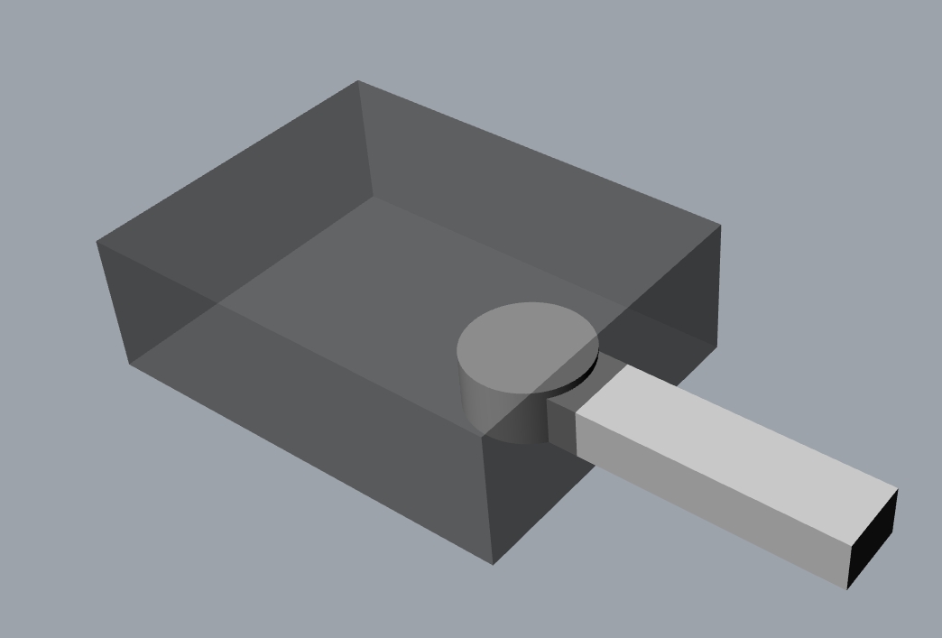
To help you understand where the blind pouch is located inside the model and how it relates to the Boolean tool, please take a look at the image below. The main body of the model is the dark gray cube. Inside it, you will find a light gray cube and a cylinder. They are the Boolean tool. The cylinder is hollow and serves as the blind pouch to hold the magnet in place.
The light gray cube cuts into the dark gray cube and creates an opening on its surface. A round magnet is inserted through this opening and ends up resting inside the hollow cylinder.
This setup makes the magnet face one way, while its magnetic pull goes another way. Thus, the magnet can be held in place without the need for glue. It helps reduce issues caused by printing tolerances and material stretches.
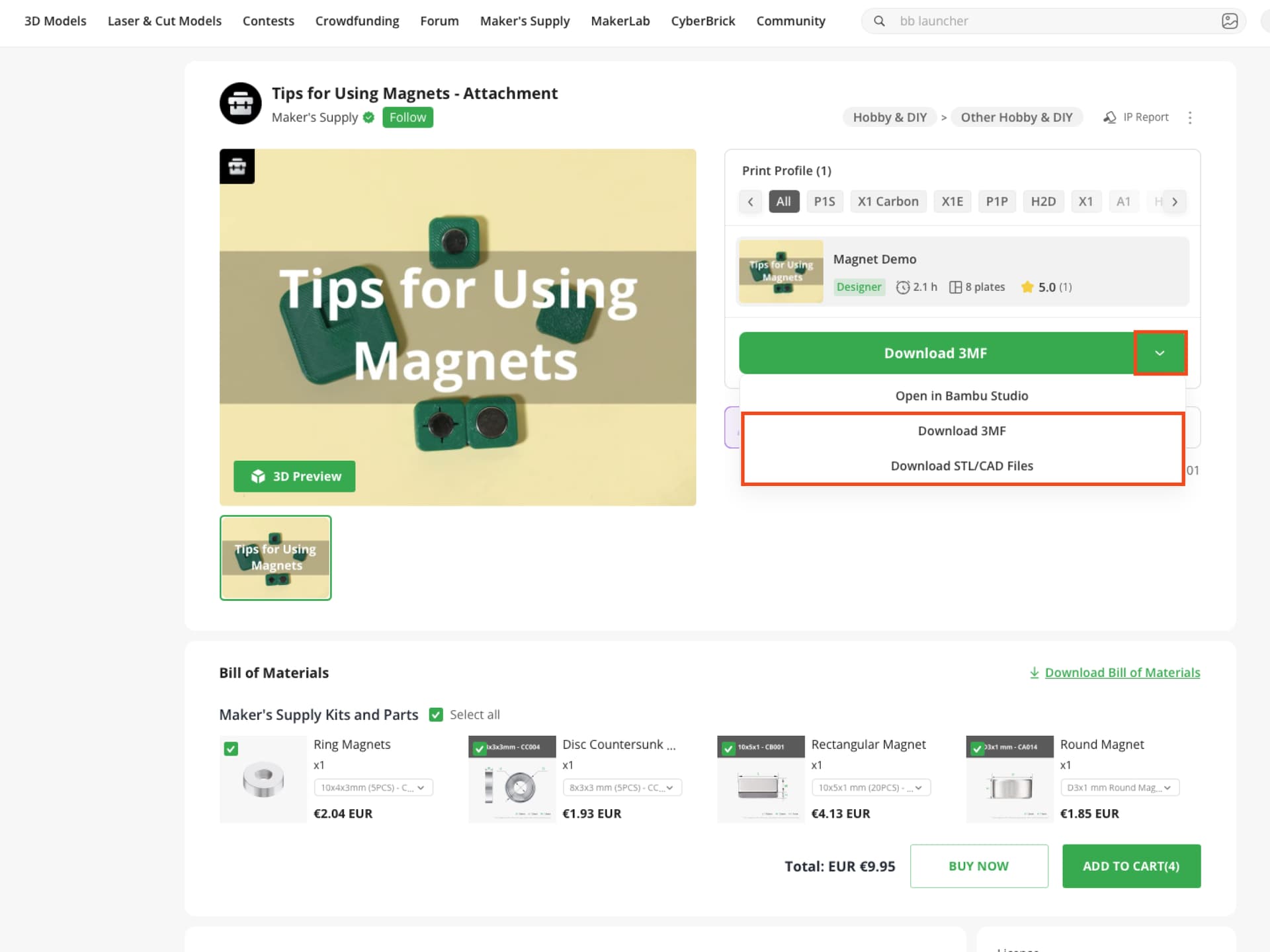
Please download the training model and the Boolean tool first. On the download page, click the dropdown arrow next to the Download 3MF button to open the menu. Then click Download 3MF to download the training model, and click Download STL/CAD Files to download the Boolean Tool (see the image below). We’ll use this 3MF file as the example for the design steps below.
1.Import the Boolean tool into the software
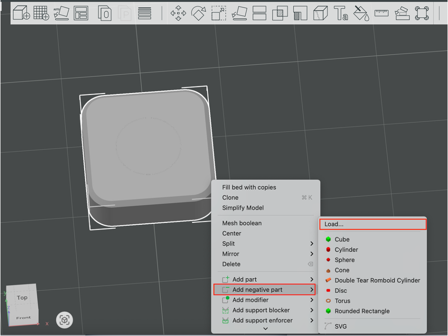
In Bambu Studio, open the 3MF file, left-click to select the part, then right-click to open the dropdown menu. Select Add Negative Part followed by Load. In this step, we need to import the Boolean Tool suitable for your magnet size (e.g., Model D8 maps to an 8 mm diameter magnet).
2.Adjust the thickness of the Boolean tool
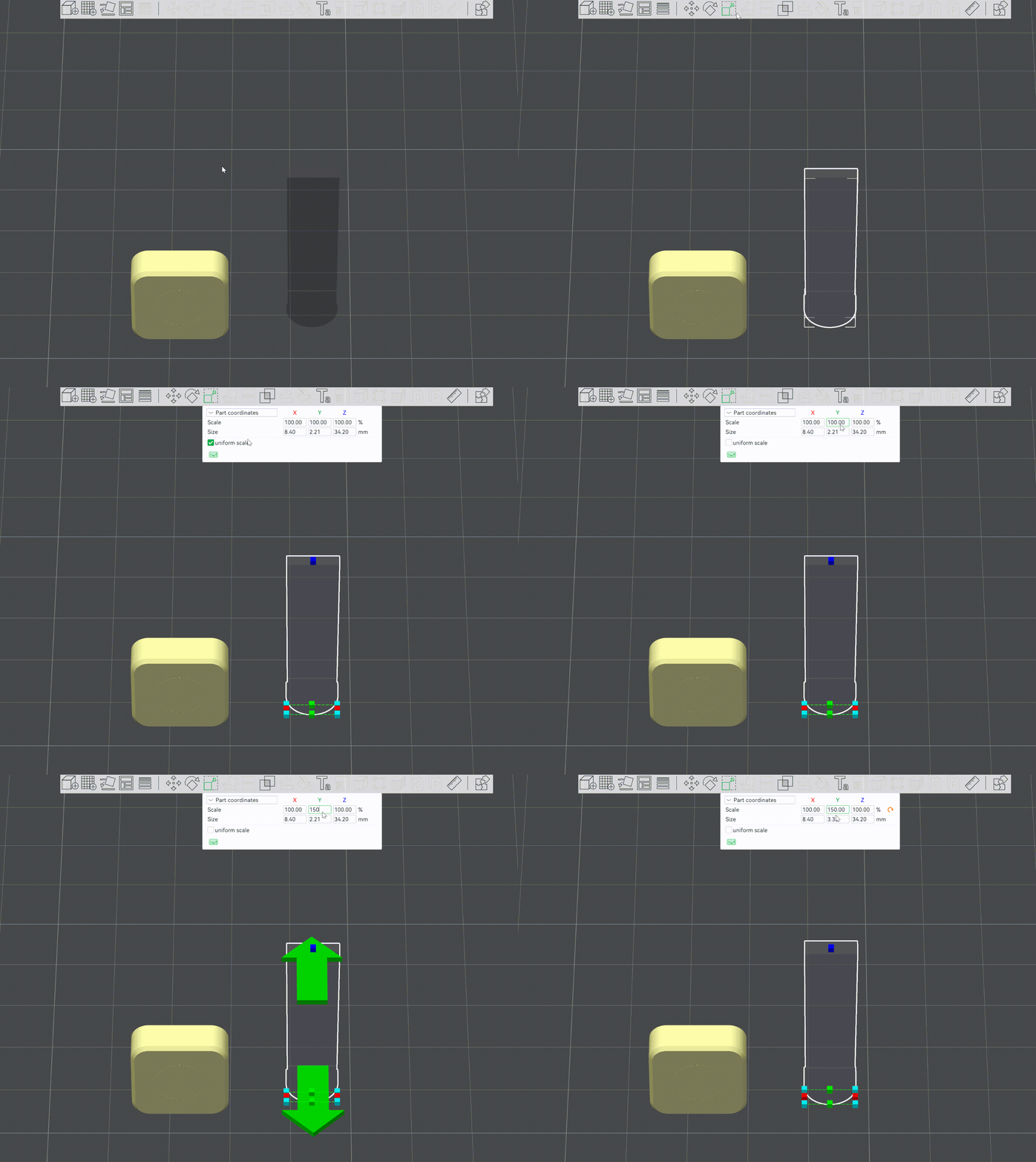
The default magnet thickness in the Boolean tool is 2 mm (Defaults to 100%). Therefore, you need to adjust the Boolean tool’s thickness to fit the actual size of the magnet. For example, for magnets with a diameter of 8 mm and a thickness of 3 mm, please import the tool file named D8 and scale it to 150%.
If you need to modify multiple magnet sockets to the same size in the same object, press CTRL+K to copy a Boolean Tool. It can help save a lot of design time.
3.Match the Boolean tool’s position to the magnet spot
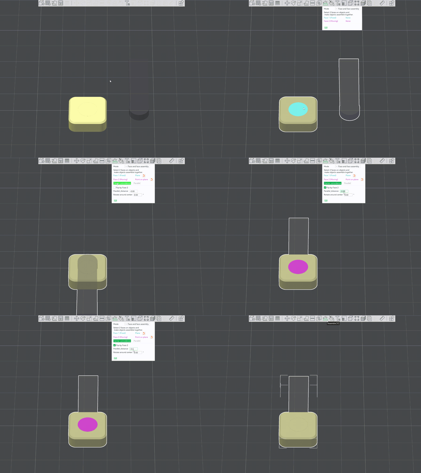
Select the Assemble tool. First, select the top of the cylinder, choose the circle below the Boolean tool, and then click Center Coincidence.
Set parameter Parallel_distance to -0.4 mm (negative value). Select the Flip by Face 2 checkbox if needed. It ensures the cylinder is positioned within the component, creating a blind pouch with a 0.4 mm thin top layer. (When the magnet diameter reaches 15 mm or more, set the top layer thickness to 0.6 mm.)
4.Rotate the Boolean tool and adjust the direction the opening faces
In the Assemble menu, use the Rotate Around Center function to rotate the opening of the Boolean tool.
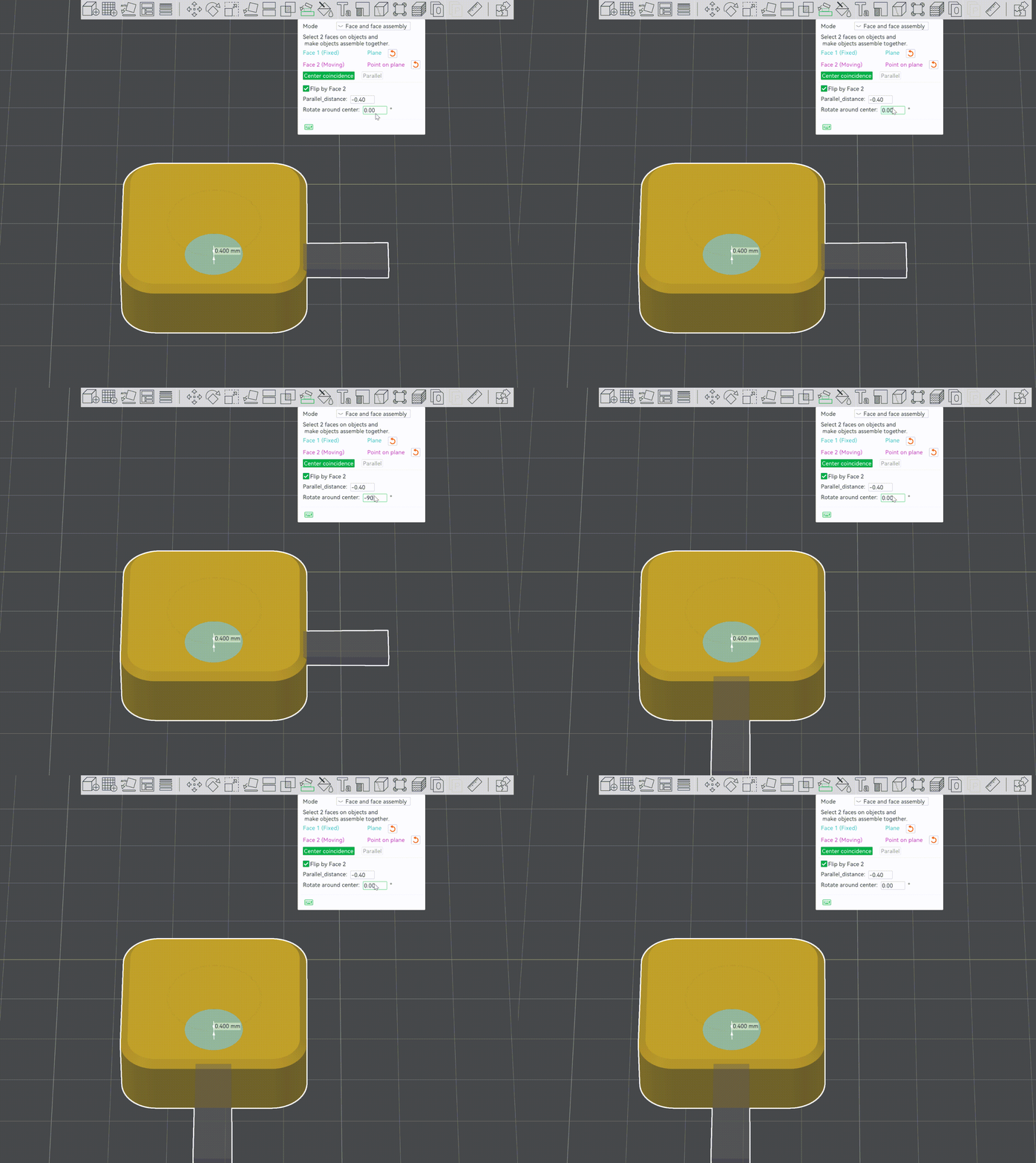
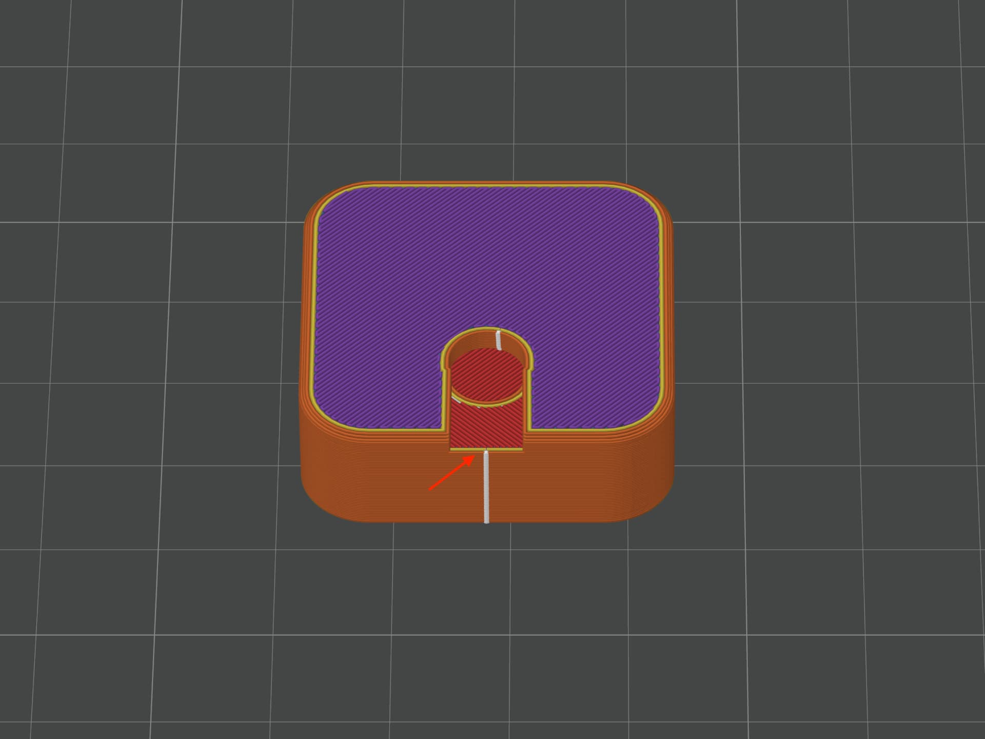
When the blind pouch lies parallel to the print plate, we recommend orienting the blind pouch opening towards the nearest edge. In the image below, the blind pouch opens toward the nearest edge.
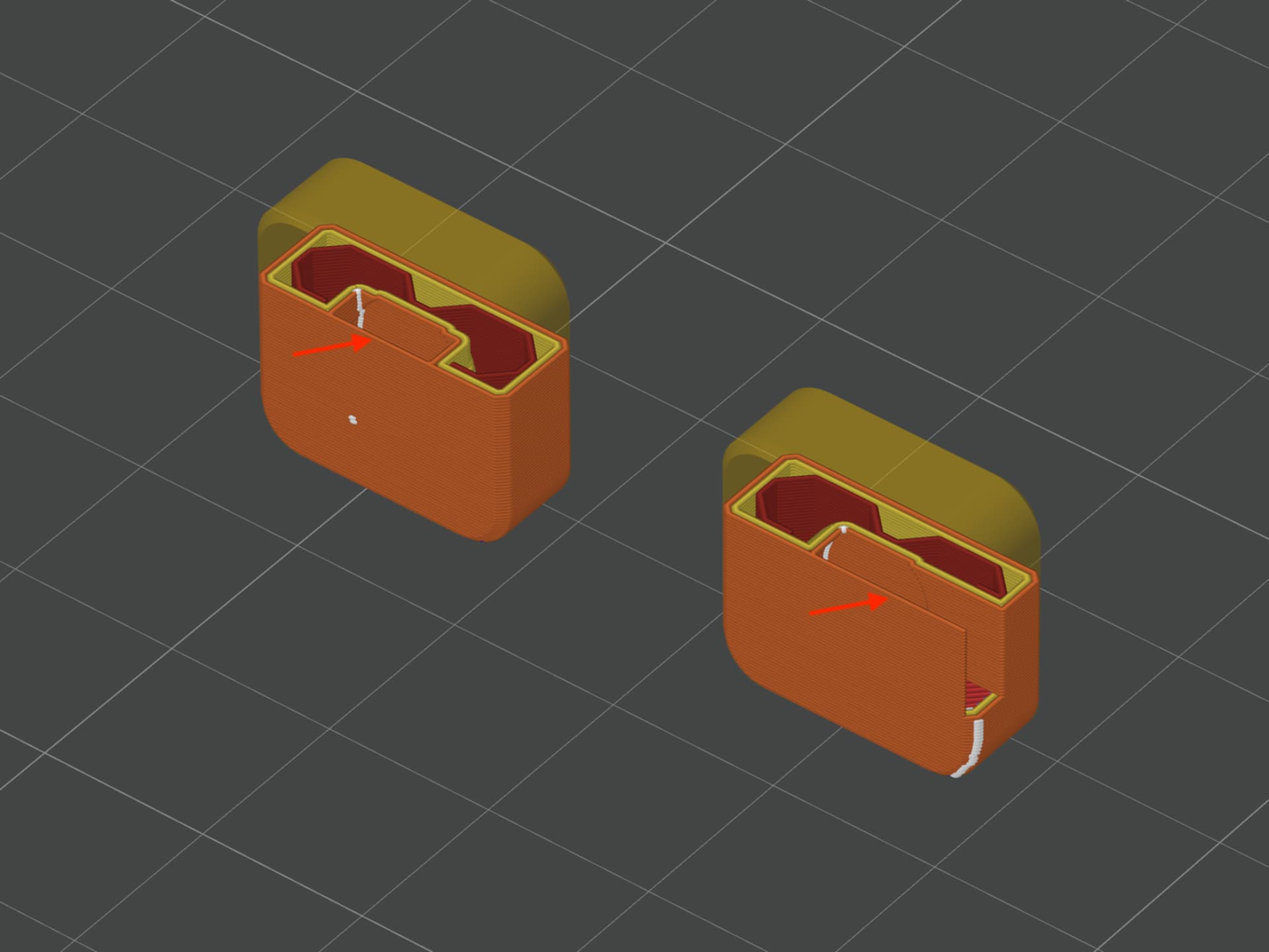
When the blind pouch is tilted or standing upright, we suggest setting its opening to face upward or downward. This step helps generate a continuous wall around the magnet, ensuring the top layer has enough strength.
After adjusting the opening of the Boolean tool, we can start to create the blind pouch. For example, you can use the Combine function in other CAD software or the Modifiers > Boolean function in Blender.
5.Import the model with the blind pouch into Bambu Studio and set up the Wall Generator
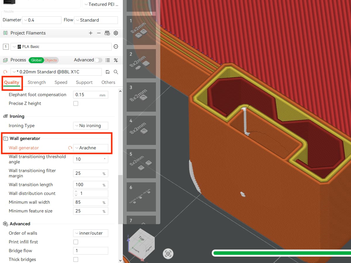
When the blind pouch is tilted, its walls will form thin horizontal layers. If the pouch walls disappear in the Preview window of Bambu Studio, click Quality in the left sidebar. Then, navigate to the Wall Generator and select Arachne to create a smooth and continuous thin wall.
The blind pouch design is now complete. Now, you can print the model and insert the magnet from the side.
Schedule a pause and embed magnets
We covered this design method, ‘schedule a pause and embed magnets’, in the article titled ‘Perfect Flush Magnet Fit’. Please check out the detailed steps and explanations provided in this article.
We have explored the causes of assembly challenges in magnet socket design and three structural design techniques to optimise a magnet socket. They are adding a relief feature, designing a blind pouch, scheduling a pause and embedding magnets. We hope these ideas and methods help you improve design accuracy and achieve smoother assembly.
These articles might help you as well — take a look!
Perfect Flush Magnet Fit
Ways to Reduce Line Detachment in Dome Structures
If this guide sparked ideas or felt familiar, share your thoughts in the comments — let’s chat! Like and save if it helped.