In Part 3, we learned how to find out the specifications of devices and power sources. We also discussed how to choose a power source with a matching output capacity.
This series has reached its fourth and final part. In this article, we will discuss these two topics.
-
Why is it important to consider the current limits of control and connection components?
-
How to choose suitable cables to connect all components?
Why is it important to consider the current limits of control and connection components?
To connect and control the devices, we need various components, such as potentiometers, power distribution boards, and CyberBrick receiver boards.
If the power source’s output exceeds what these components can handle, it may cause an overload or damage. Thus, when choosing control and connection components, we need to consider their current limits (see the image below) and the device’s current requirements.
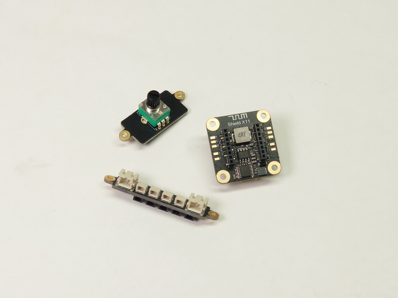
Let’s check out one case together. We will see how to consider the current limits of both the control and connection components.
Current limit of control components
Now, let us understand and assess the current limit of each component.
-
N20 motor LA002 x 1 pcs
-
COB light strip KA009 (300mm each) x 3 pcs
-
Potentiometer IA007 x 1 pcs
-
4-channel power distribution board IA005 x 1 pcs
The N20 motor may require 0.25A to 0.40A during high-power usage. A COB light strip (300mm long each) needs around 0.22A. The required current might hit 1.1A if regulating all lights and the motor’s rotational speed with a potentiometer IA007. But the current limit of the potentiometer IA007 is 0.4A.
If controlling all lights and the motor’s rotational speed by connecting a potentiometer IA007 to a distribution board IA005, excessive power usage may cause these risks.
-
Circuit protection may fail to trigger.
-
After increasing the voltage, the excess current may damage the transistor.
In this case, we can use separate potentiometers for the LED light strip and motor.
A potentiometer boosts the voltage through a transistor.
When the potentiometer limiter is set to its highest setting, the device voltage is a bit higher than when it is directly connected to a power source. When using a potentiometer IA007, consider calculating the required current for your device. Multiply 1.5 to factor in transistor efficiency and voltage overload. This helps ensure stable operation within its regulatory range.
For example, a COB light strip KA009 (300mm long each) requires 220mA at 5V. When using the potentiometer IA007to control the light strip, the current rises to 330 mA at 5V. This is calculated by multiplying 200 mA by 1.5.
Current limit of connection components
Some connection components support connecting more devices. For example, a 4-channel power distribution board IA005 and a CyberBrick receiver shield XA004.
When using these connection components, please keep their safe working current in mind. Stay under the current limit to avoid damage.
For example, you can connect a 4-channel power distribution board to a potentiometer, a motor, and COB light strips. The potentiometer controls the N20 motor’s rotational speed.
Let us calculate the total demanded current of these devices. The demanded currents for these devices are:
-
One N20 motor controlled by a potentiometer. Its required current is 0.37A - 0.6A. This is 1.5 times the 0.25A~0.4A range.
-
Three COB light strips KA009 (300mm each). Each COB strip requires 0.22A.
The total current demand is 1.03A - 1.26A. It exceeds the 4-channel power distribution board’s current limit of 1A. Thus, it may trigger the power distribution board’s current protection.
To lower the total current demand, we can either shorten the light strip or add another power distribution board.
Examples
We’ve summarised the control and connection components needed for these models using the methods above. Please see the table below for more details.
-
Retro Observatory - small desk setups
-
360˚ Rotating Marble Run - Enclosed with Lights - big desk setups
-
Formula Vintage - CyberBrick - CyberBrick RC car
-
Remote Controlled Water Turret - Composite RC model
Retro Observatory - small desk setups

Source: 邦德不喝可乐, Retro Observatory, MakerWorld, 2025. Retrieved on Dec. 31, 2025, MakerWorld
This connection component is suitable for the function below.
Connection component: Rechargeable Power Kit-ZC003 Board x 1
Specification: 3.7V, 1A
| Function | Device | PCS | Voltage | Current |
|---|---|---|---|---|
| Turn the wall lamp on | 4 White 3030-LED Board with SH1.0 Connector 5V-KB001 | 4 | 3.7V-6.0V | 60mA (5V) |
| Total | - | 4 | 3.7V | <240mA |
360˚ Rotating Marble Run - Enclosed with Lights - big desk setups

Source: MaKim, 360˚ Rotating Marble Run - Enclosed with Lights, MakerWorld, 2024. Retrieved on Dec. 31, 2025, MakerWorld
This connection component is suitable for the functions below.
Connection component: Power Distribution Board - 4 Channels-IA005 x 1
Specification: 3.7V-6V, 1A
| Function | Device | PCS | Voltage | Current |
|---|---|---|---|---|
| Turn the light post on | COB LED Strip Light 300x1mm-KA009 | 1 | 3.7V-6.0V | 20mA (5V) |
| Rotate and lift the balls | N20 Single Shaft Worm Gear Motor 25rpm-LA008 | 1 | 3.0V-7.0V | <0.16A (6V) |
| Total | - | 2 | 3.7V-6V | 0.26A |
This control component is suitable for the function below.
Control component: Potentiometer Board-IA007 x 1
Specification: 7.4V, 0.4A
| Function | Device | PCS | Voltage | Current |
|---|---|---|---|---|
| Rotate and lift the balls | N20 Single Shaft Worm Gear Motor 25rpm-LA008 | 1 | 3.0V-7.0V | <0.16A (6V) |
| Total | - | 1 | 3.7V-6V | 0.26A |
Formula Vintage - CyberBrick - CyberBrick RC car

Source: Kocyns, Formula Vintage - CyberBrick, MakerWorld, 2025. Retrieved on Dec. 31, 2025, MakerWorld
This connection component is suitable for the functions below.
Connection component: Remote Control Receiver Shield-XA004 x 1
Specification: 7.4V-12.6V, 3A max
| Function | Device | PCS | Voltage | Current |
|---|---|---|---|---|
| Remote control | Multi-Function Controller Core-XA003 | 1 | 7.4V – 12.6V | 300mA |
| Turn | 9g Servo motor 180°-PG001 | 1 | 5V (XA004) | 700mA |
| Go forward | 030 Micro DC Motor with SH1.0-LA024 | 2 | 5V-9V | 250mA |
| RGB tail light | WS2812 RGB LED-KB003 | 2 | 5V (XA004) | 36mA |
| Total | - | 6 | 7.4V-9V | ~1.3A (7.4V) |
Remote Controlled Water Turret - composite RC model

Source: MaKim, Remote Controlled Water Turret, MakerWorld, 2025. Retrieved on Dec. 31, 2025, MakerWorld
This connection component is suitable for the functions below.
Connection component: Remote Control Receiver Shield-XA004 x 1
Specification: 7.4V-12.6V, 3A max
| Function | Device | PCS | Voltage | Current |
|---|---|---|---|---|
| Remote control | Multi-Function Controller Core - XA003 | 1 | 7.4V – 12.6V | 300mA |
| Adjust the water gun’s left/right movement | 9g Servo motor 360°-PG002 | 1 | 5V (XA004) | 550mA |
| Adjust the water gun’s up/down movement | 9g Servo motor 180°-PG001 | 1 | 5V (XA004) | 700mA |
| Press the trigger to shoot | 9g Servo motor 180° - PG001 | 1 | 5V (XA004) | 700mA |
| Status light | WS2812 RGB LED-KB003 | 3 | 5V (XA004) | 36mA |
| Total | - | 7 | 7.4V | 1.7A |
| Shoot a water stream | Electric Water Spray Kit 01-ZC004 | 1 | 7.4V | 1A (average)、2.4A (peak current) |
The function below does not require a connection component.
| Function | Device | PCS | Voltage | Current |
|---|---|---|---|---|
| Shoot a water stream | Electric Water Spray Kit 01-ZC004 | 1 | 7.4V | 1A (average)、2.4A (peak current) |
How to choose suitable cables to connect all components?
Once we’ve confirmed that each device’s current requirements are met, we now need to connect each interface with the matching cables (see the image below).
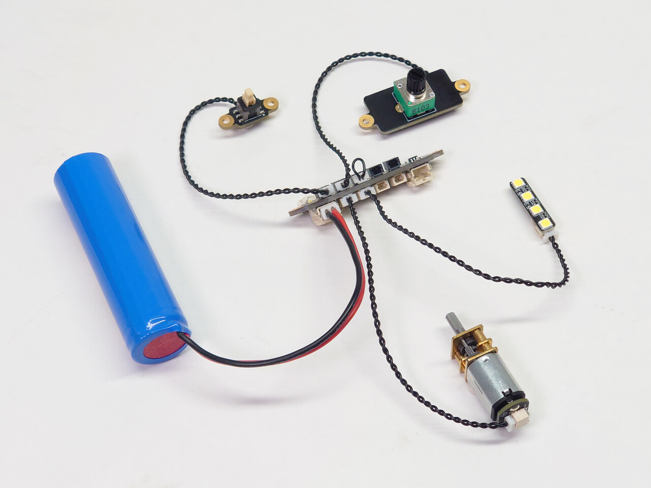
For example, the N20 series motor terminals and the channel ports on the 4-channel power distribution board use SH1.0 2P female connectors. To connect a N20 series motor to a 4-channel power distribution board IA005, you can use the SH1.0 2P male-to-male wire (IC004). It links the motor terminal to the channel port.
This wire comes with the N20 motor package.
If the ports at both ends are different, we need to connect with either an adapter cable or a board. In everyday life, you may use adapters to convert XH2.54 (wide plug) to PH2.0 (narrow voltage power). It is also common to connect PH2.0 power directly to SH1.0 devices.
Besides, the adapter board helps extend cables (see the image below). For example, the SH1.0 2P adapter board is ideal for a large model.
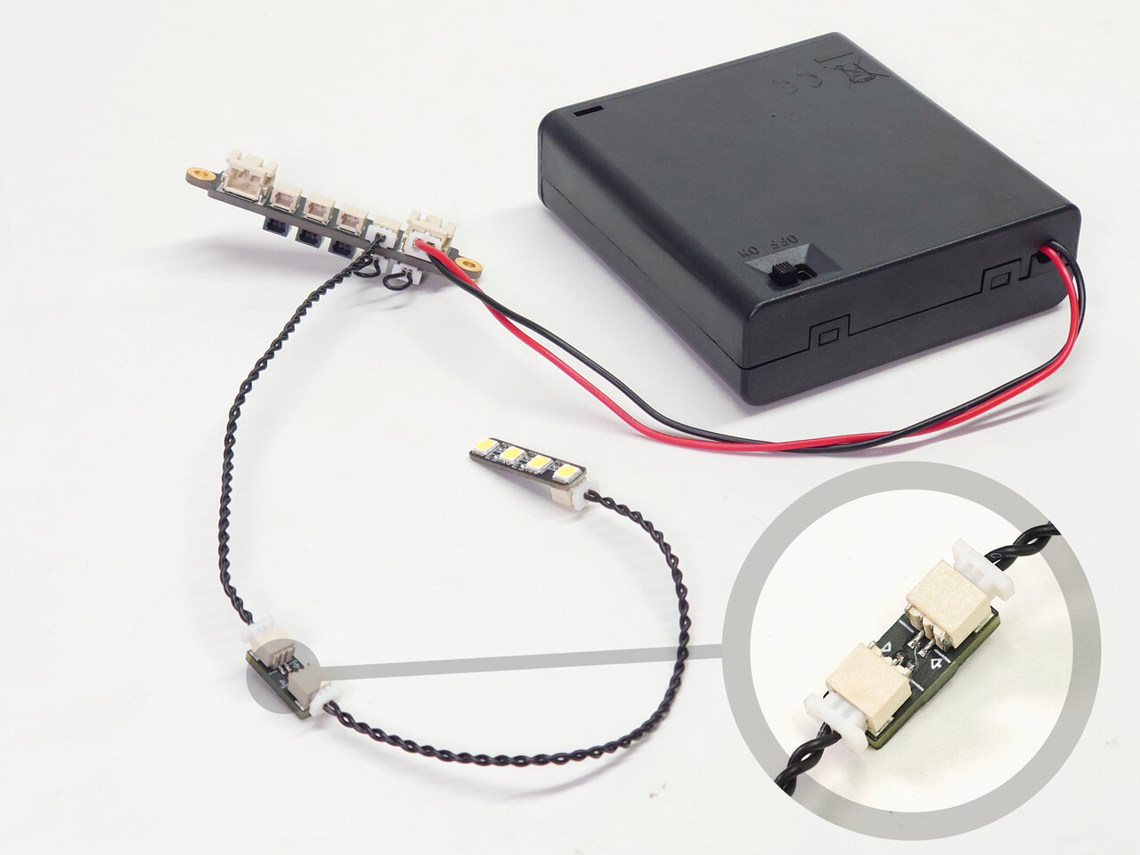
Please check the list below for connecting cables needed for common setups.
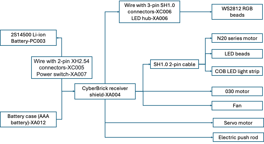
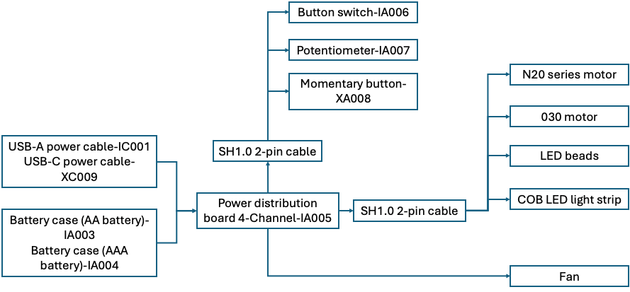
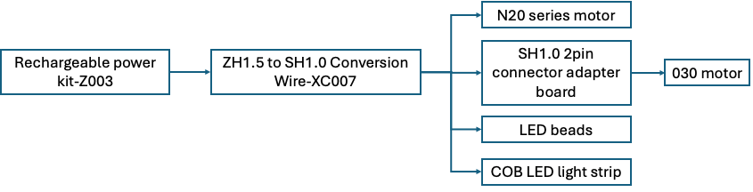
Please check the product detail page for each electronic component or the instructions. It provides detailed instructions, connection guidelines, and examples.
In this article, we have explored why it is important to consider the current limits of control and connection components, and how to choose suitable cables to connect all components.
By the end of this article, we completed our exploration of the power system plan series together. We hope these ideas and methods help you find the right way forward and save time when choosing a power source.
These articles might help you as well — take a look!
Power System Plan: Models Come Alive! #1
Power System Plan: Models Come Alive! #2
Power System Plan: Models Come Alive! #3
If this guide sparked ideas or felt familiar, share your thoughts in the comments — let’s chat! Like and save if it helped.